More
Strippit Super 30/30
Punch-Head Repair Notes!
This Webpage is a Continuation of my Webpage Super 30/30 Punch-Head Notes
which You Should Carefully Read First!
These Punch-Head Notes Apply also to All
Sonic 18/30, Custom 18/30, Custom 30/30, Custom 30/40-Mechanical,
Super 30/40-Mechanical, as well as the Most Popular Super 30/30 Punch Machine.
You should start by Reading the Operation & Maintenance Manual to familiarize
yourself with How the Punching Mechanism of these Machines actually works.
If You can't be Bothered to Obtain a Manual, Read-It, and at least Attempt to
understand your Machine's Problems, Don't Expect Me to Bother Much to Help You.....
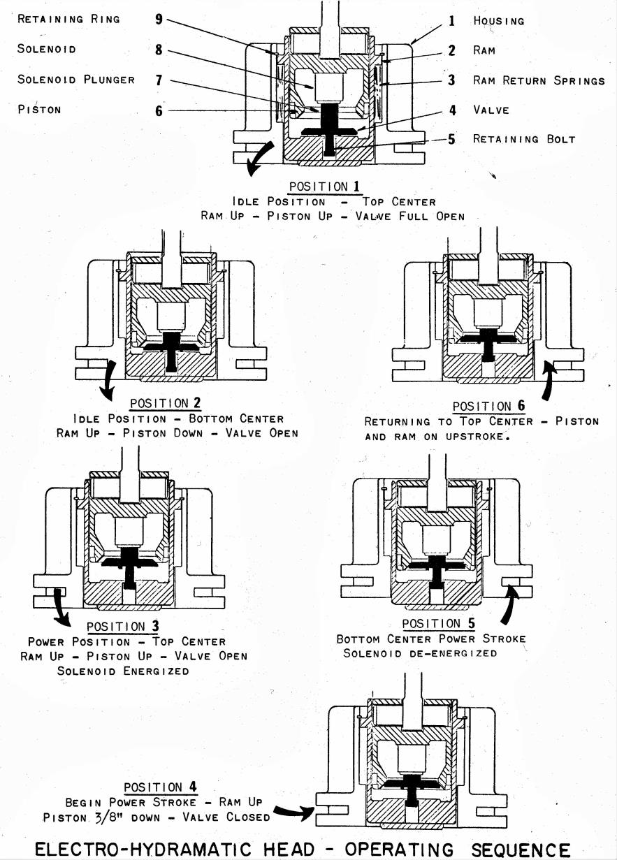
Below is a Basic Pictorial on How these Machines Punch, But
does not go into Timing Sequences provided by Limit Switches & Relays.
Again, there is more Detailed Description of Machine Operation in the Manual.
Problem;
12F --- Varying Short to Normal Stroke in Single, Normal Operation in Nibble.
--- Caused by Limit Switch LS1 Short. LS1 is Normally-Open & Closes when Activated!
--- But, Can Also be caused by Too-Thick Oil in Punch-Head, as Too-Thick Oil does
Not flow Back & Forth fast enough through the Bottom of Piston when Valve is Open.
For Many Decades, Strippit has recommended
Mobil DTE-24 Hydraulic Oil which is a ISO 32 Weight Hydraulic Oil.
Do NOT Confuse the International Standard ISO with the U.S. Standard SAE
ISO 32 = SAE 10WT
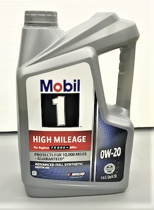
Recently, I have switched to using Mobil-1 0W-20 SAE Motor Oil in the Punch-Head;
--- I think it gives More Lubrication Protection to Valve & Piston Valve-Seat, and I have
been finding more Valve Seating Wear Problems on these 30 to 65+ year old Machines.
--- It's Easy to find Mobil-1 0W-20 here in the U.S. in handy 1 Quart Containers.
Problem;
Oil Sprays-Out Top of Piston when Punching High-Tonnage Holes.
--- Usually caused by Poor-Fitting or Worn Valve & Piston Valve-Seat
--- Also caused by Worn-Out Packing-Ring Seals on Piston, Get Rebuild Kit!
--- Other possible cause is a Cracked Piston from Too Many High-Tonnage Punches,
and I Do See Cracked Pistons from time to time.
Lets Review YOUR Junior High-School Math Class Skills & See if You Paid Attention!
Punch Piston is 4.750" in Diameter so Radius of Punch Piston is 4.750 /2 = 2.375"
Area of a Circle is = Pi x R squared
Area of Punch Piston = 3.1416 x 2.375 squared = 3.1416 x 5.6406 = 17.72 Square-Inches
If we are Punching a 30-Ton Hole, that equals 30 x 2000 = 60,000 pounds of Force!
Divide 60,000 by 17.72 = 3,386 Pounds per Square Inch and
That 3,386 PSI is the Pressure of the Oil Between Piston and Ram!
With that Very High-Pressure
If there is Any Wear or Misalignment of Valve & Piston Valve-Seat,
Oil will Shoot Past Valve Violently up into Piston and out Past Baffles on Top of Piston!
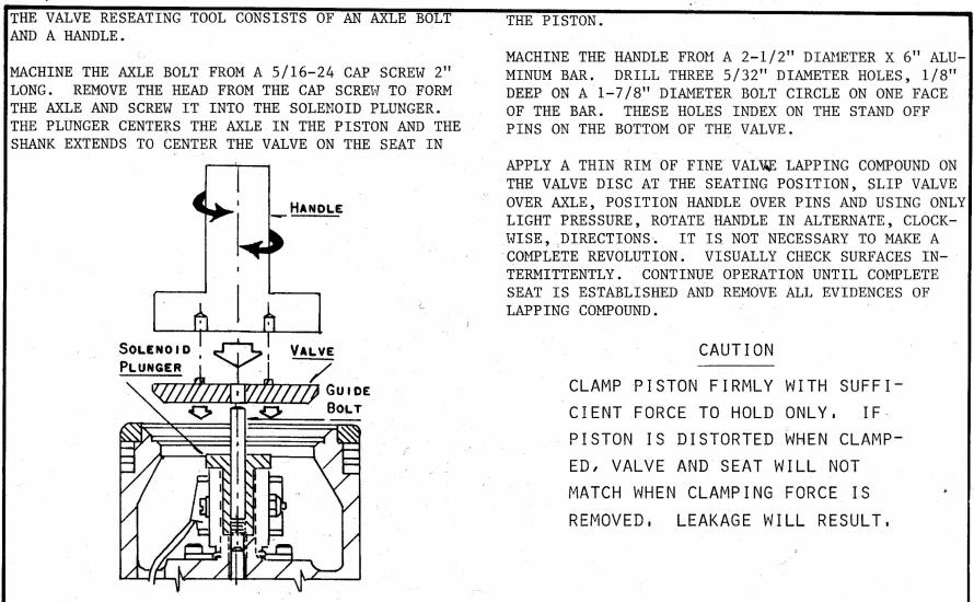
ONLY Solution is to Carefully Hand-Lap Valve to Piston-Seat per Strippit Manual
to Re-establish a Good Seal! Read The Manual!
We had Customers that had The Oil Splashing Out Top of Piston Problem.
They Disassembled Punch-Head, took out Piston, Carefully Lapped Valve & Piston-Seat,
reassembled Punch-Head, Did this 2-Times, and it Fixed their Oil Splash Problem.
--- When in Doubt, Change The Oil! I would also change Piston / Ram Oil once a year!
-- See the Diagram on my Webpage Un-Jam Strippit Super 30/30 Punch Machines
-- Remove Swing-Arm Punch Holder from Machine
-- Remove 2 Lock-Pins from Swing-Arm Holder and Lock the 2 Pins back in Machine
with the 2 Handles. This will Close LS4 Switch to allow Punching.
-- Put a Bowl under Ram to catch Check-Valve Ball and Oil
-- Remove 5/16"-18 Set-Screw, Item #15, usually Located on Bottom Left-Side of Ram
-- Ball usually will Not just Fall-Out, so
Turn Machine on and Punch 1 or 2 times. Ball should Fall or Shoot into bowl.
-- Oil will slowly drip out, I usually let it drip out overnight until empty
-- Put Ball back and Carefully (Don't Cross-Thread!) Thread Set-Screw back into Ram
-- Refill Piston with Correct Oil to Correct Amount using your Dip-Stick!
So the LS1, and LS2, Mechanical Timing Switches are Activated for Only About 28ms
Expressed Another Way,
28ms = about 1/36th of a second, and In that Tiny Bit of Time,
--- LS1 Normally-Open Switch Contacts on Left Flywheel Must Close,
--- Sending A.C. Power to CR1 Relay Coil,
--- CR1 Relay then has to Very Quickly Pull-In and
--- CR1 Relay's Set of Auxiliary-Contacts have to Close and
--- Get A.C. Power from Normally-Closed 2LS Switch Contacts on Right Flywheel
back to CR1 Coil to Lock-In CR1 Relay Before LS1 Releases
--- All has to happen Before the 28ms Closure Time of LS1 Switch is Over, Or
--- If it does Not Happen Correctly in the 28ms, you get No Punch or Short-Stroke Punch
So it's Easy to see that These Parts are Critical, So Check for:
--- Bad or Worn-Out Mechanical Switches
--- Worn-Out Switch-Arms
--- Incorrect or Wrong Type of 1LS or 2LS Switch
--- LS1 or LS2 Wired-Wrong
--- Worn Switch Cams
--- Bad Mag-Switches or Broken Magnets, if Machine is so Equipped
--- Bad or Worn-Out or Slow CR2 Relay
--- Bad or Worn-Out or Slow CR1 Relay
--- Incorrect Replacement Motor that is NOT 1140 RPM
These Parts, if Bad or Worn, can Cause
Many Punching and Short-Stroke Stroke Problems.
That's why when I am Working on Punching Stroke Problems
I Carefully-Check and Start Repairs with;
--- Replacing LS1 & LS2 Switches and Cams, or Mag-Switches
--- Change the Oil in Punch-Head
--- Change CR2 Relay
--- Change CR1 Relay
--- Check for Low Transformer Output-Voltage on Machine;
--- Wired to Low 208VAC 3-Phase Electric Systems, instead of 230 / 460
--- Having a Too-Small Replacement Transformer fitted,
Needs to be at least .25 KVA, .35KVA or .50 KVA is Better!
--- Transformer Output Voltage should be about 110 to 125 VAC
I'm switching to using Mobil-1 0W-20 Oil in Piston / Ram.
It's Easy to find Locally and
I think it Lubricates Better to Slow-down or Stop Valve & Piston-Seat Wear.
Do NOT use any Heaver Oil than Mobil DTE-24 or Mobil-1 0W-20 !!!
Having The Correct LS1 & LS2 Timing Switches in Good-Condition
and
CR1 & CR2 Relays in Good-Condition
is Critical to
Proper Consistent Punching with No Partial Short-Stroke Punches!
Time for Even More Fun Math!
And I will Show you Why
Good Switches & Relays are so important on these Machines.
On Super 30/30 Machines, the 2 Flywheels are 18.5 inches in Diameter.
But, LS1 & LS2 Timing Switch Cams are 2 Inches Inside the Flywheel Out-Side Diameter
So, the Diameter that Switch Cams Travel is 18.5" - 4" = 14.5" Switch Cam Travel Diameter
I want to know the Linear Distance that the Switch Cams Travel
in Circumference in this Case, in 1 Revolution of Flywheel.
Radius is Half of Switch Cam Travel Diameter 14.5" /2 = 7.25" Switch Cam Travel Radius
The Formula for finding Circumference is C = 2 Pi x Radius
Circumference = 2 x 3.1416 x 7.25 = 6.2832 x 7.25 =
= 45.55 Linear Inches that the Switch Cams Travel in 1 Revolution
The Strippit Maintenance Manuel states that Machine can Punch 165 Strokes a Minute which means Flywheel is turning 165 rpm (Revolutions Per Minute). I checked my Machine by probing the LS1 Switch with my Digital Oscilloscope and I measured about 166 RPM, Remarkably Close! So, I will use 165 RPM Flywheel Speed Number in my calculations.
A millisecond (ms or msec) is one thousandth of a second.
1 Minute has 60 seconds = 60 x 1000 = 60,000ms.
If we Divide 60,000ms by 165rpm we find that 1 Revolution takes 363.636ms
and that the
45.55 Linear Inches that Switch Cams Travel Path in 1 Revolution takes same 363.636ms
and that Time of
363.636ms Divided by 45.55 Linear Inches that the Switch Cams Travel
gives you the Time of 7.983ms per inch of Switch Cam Travel.
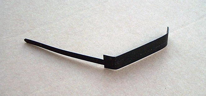
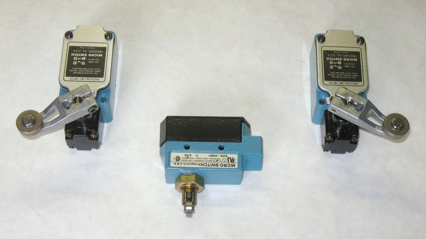
Measuring from Half-Way Up the Start-Slope of a Switch Cam to
Half-Way Down the End-Slope of Switch Cam is 3.5 inches, See Photo Below.
A perfect LS1 or LS2 Mechanical Timing Switch would be activated for about that
3.5 inches x 7.983ms per inch = 27.94ms. = About 28ms, Not Very Much Time!!!
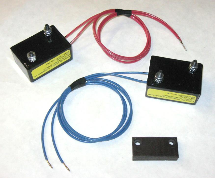
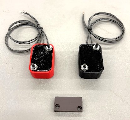
#19274-000 Normally-Open Mag-Switch RED-Wires (Old Square-Box Type) or
RED Curved-Box New-Type. LS1 is on the Left Side
#19275-000 Normally-Closed Mag-Switch Blue-Wires (Old Square-Box Type) or
BLACK Curved-Box New-Type LS2 is on the Right Side
#105092-000 Magnet 2 are used, 1 Magnet is Mounted on each Flywheel
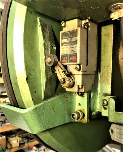
Mechanical LS1 on Left, LS3 in Middle, Mechanical LS2 on Right
#49790-040 #12979-000 #49790-040
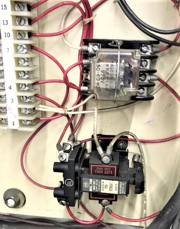
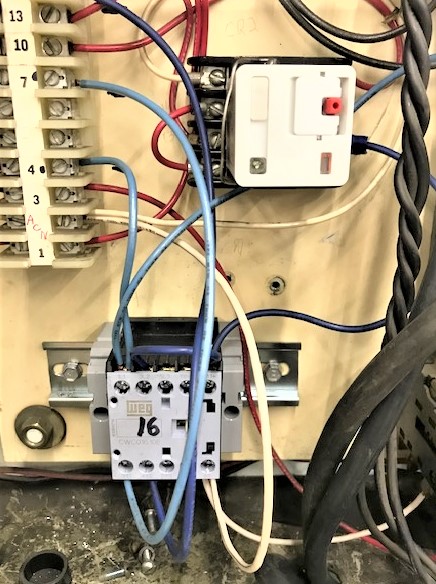
Bottom Black-Relay in ABOVE Photo is Original CR1 Type that Strippit used.
I'm Amazed it Ever Even Worked in these Machines as the 28ms Time-Window to
Close-Contacts to Lock itself in is So Short! This Allen-Brady Relay is No Longer Made,
So Replacement Must use our CR1 Retrofit Relay Kit
Bottom Gray-Relay in Photo BELOW is our Replacement CR1 Relay Retrofit
and Specifications say that it can Fully-Close in only 16ms, Very Fast!
Strippit Machines were Wired MANY Different Ways over 40+ Years of Production.
So, we Cannot tell you Exactly how-to wire-in our Replacement CR1. It's Not that hard,
But Has to be Installed by Someone who Understands Electricity & Wiring,
as Wiring Variations Need to be Figured-Out at Installation!
========================================================================
Upper Clear-Relay in ABOVE Photo is Original Plug-In CR2 Type that Strippit used.
It just Plugs into a Socket so it can be Easily Replaced in Seconds!
Upper White-Relay in Photo BELOW is our Replacement Plug-In CR2 Relay.
It Also has a Light that Lights-Up when Relay is Pulled-In
to help make it Easier to Troubleshoot Problems.
This page was last updated: April 29, 2026


MAG-Switches

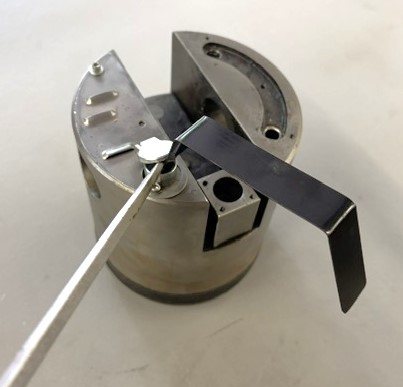
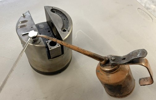
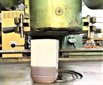
Set Oil to Correct Level in Punch-Head with the Dip-Stick!
My Photos Here show a Piston out of Machine for Clarity.
You, of Course, will do this with Piston in Your Machine.
Concept is Simple;
--- Hold the Spring-Loaded Trap-Door On Top of Piston "Open"
using a Long Thin Flat-Blade Screwdriver.
The Door may or may not be Missing on your Machine's Piston.
--- Then Insert Dip-Stick or Oil Can to Measure and Fill Piston
with Proper Type Oil to Proper Oil Level per Instructions
--- Rotate Right Flywheel Until Scribed "B.D.C. Line" (Bottom Dead-Center)
Is Lined-Up with Bottom of Electrical Box.
MUST Use #49579-000 Dip-Stick !