Un-Jam Your Strippit
Super 30/30, Custom 18/30,
Super 30/40-Mechanical, and
Sonic 18/30 Punch Press Machines!
From Time to Time, Machine Operators will Overload and Jam-Up the Strippit
Single-Station Punch Machine they are Operating. Usually by, Trying to Punch
Too-Thick of Sheet-Material, a Punch Too-Large for Sheet-Material, Wrong Die Clearance, Wrong Die, Wrong Punch, Dull Punch & Die, Crossed Punch & Die, etc.
Punch will be "Stuck-Down" with Machine Not finishing Punch-Stroke,
Punch is Stuck in Sheet-Material and Punch-Ram is Hard-Against Top of Punch.
And You Can Not Remove Sheet-Material, Punch, or the Swing-Arm Holder.
This is because you Now have OVER 30-Tons of Force Springing & Gapping
Machine C-Frame like the Large Spring that it is.
All of this Force is now directed through the Ram to Punch and Sheet-Material,
So, of course you can not get it out!
Now this is when your Rocket-Scientist Operator & Maintenance Guys
get-out their Big Hammers & Pipes & Pry-Bars & Acetylene Torches to try
to Pry-up the Ram, Rotate Flywheels, Cut Out Tool, to "Fix" the Jam.
Instead, they just Damage Machine & Swing-Arm Holder & Tooling.
If they Damage or Break the Swing-Arm Holder,
you are Out--Of--Business as they are NOT Manufactured anymore!
As an aside,
I would Build a Very Solid Stand Next to my Punch Machine with
2 Good Wood-Box Holder-Places for Both of my 1 1/4" & 3 1/2" Swing-Arm Holders.
Because lazy Operators usually just leave Swing-Arm Holder that they are not using
on Machine Table. Sooner or Later, will then accidentally Knock-it onto the Floor
and it will Break-In-Two Pieces that Can NOT be Repaired!
If Operator & Maintenance Guys Bothered to Read Machine Manual,
( You Do Have a Machine Manual, Right??? )
they would see they could-have
Simply Relieved the 30-Tons of Jammed Punch Pressure by;
1 -- Taking a 5/32" Allen Wrench
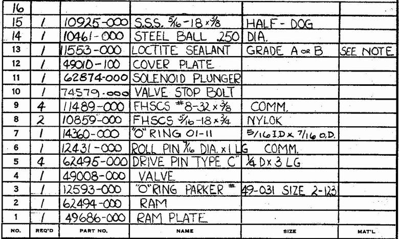
2 -- Very Slowly Backing-Out 5/16"-18 Set-Screw, Item #15, usually
Located on Bottom Left-Side of Ram.
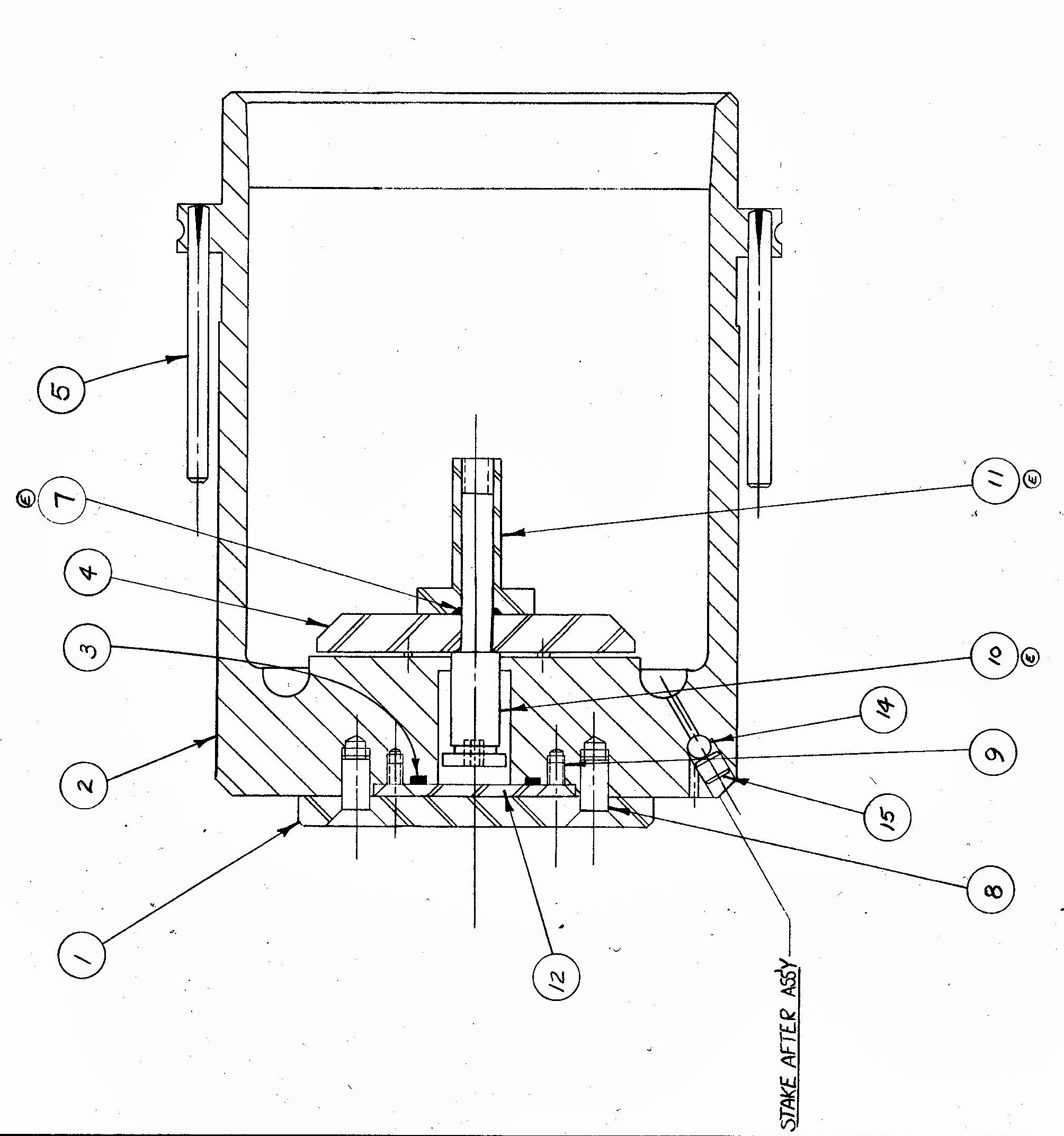
3 -- This Un-Seats the 1/4" Ball, Item #14, acting as a
Check-Valve to Ram Oil Chamber. See Ram Assembly Drawing Below!
4 -- This allows Trapped-Oil, Under Tremendous Pressure, Use Caution!,
in Punch-Ram to be Slowly Drained-Out,
and releasing the 30-Tons of Force from Jammed Sprung Machine-Frame.
Frame will Un-Load and Ram should Rise as Oil is Slowly Drained-Out.
5 -- You should now be able to Remove Swing-Arm & Tooling & Sheet-Material
6 -- Carefully Reinstall the Ball & Set-Screw, Don't Cross-Thread Screw!
7 -- Using #49579-000 Punch-Head Dip-Stick,
Refill Punch-Head at Bottom-Dead-Center with
any Good ISO-24 Weight Hydraulic Oil
or my New Favorite Mobil-1 Synthetic 0W-20 SAE Motor Oil
Do NOT Use a Heaver Grade Oil!
8 -- Now Correct the Original Problem that Caused Jam in the First-Place!!!
9 -- Also Check that 2 Drive-Belts were Not Shredded when Jam occurred,
Replace belts if necessary.
And, if Press Motor will Not Start, Motor Overload-Breaker in Electrical Box
on side of Machine probably has Tripped,
just Press-In Re-Set Plunger to Re-Set Breaker.
Try Not to Electrocute Yourself.
You should now be Back in the Punching Business! Be More Careful Next Time.
This Simple Pressure-Relief Valve is Built-In to All Strippit
Super 30/30, Custom 30/30, Custom 18/30, Sonic 18/30,
Pre-1977 Super 30/40-Mechanical and Custom 30/40-Mechanical Machines.
After 1977, Super 30/40-Hydraulic and Custom 30/40-Hydraulic Machines
were Redesigned to be Completely Hydraulic Punch Presses.
Very easy to tell them apart as
Mechanical Machines will have 2 Flywheels in Front of Machine, and
Newer Hydraulic Machines will NOT have any Flywheels at all.


This page was last updated: May 18, 2025


And Remember,
Don't Let Your Women Have Chewing Gum!


The Cut-Away View of the Above Ram can be Confusing as it is a
Side-View, Not the Front-View that would Face-You
with the Ram in your Machine.
Set-Screw of Relief-Valve is Actually on the Left-Side of Ram,
in the Area where the Notch or Cut-Out of Casting is
when the Ram is in Machine.
Sometimes it is Hard to find the Set-Screw Hole
as it is probably filled with a Half-Century of Grease and Dirt.
Also, Be Aware that this Assembly and Parts
Changed and Evolved somewhat
over the 4-Decades these Machines were Built!
You Actually do NOT have to Back-Out and Remove Set-Screw and Ball,
All the Way Out, to Release Oil Pressure.
As you Slowly Un-Screw Set-Screw,
The Ball will Move-Down with Set-Screw,
and Un-Cover a Small Drilled-Hole Passage-Way
where the Oil will Shoot Downward Releasing Pressure.
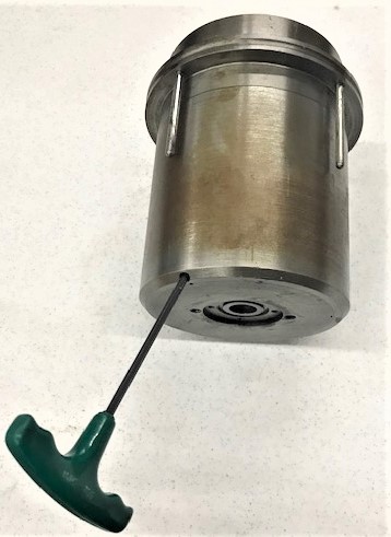
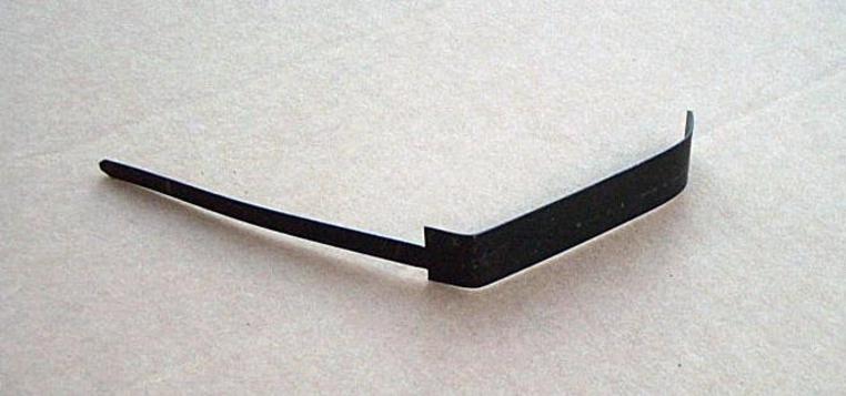
You can See Small Release-Hole in the
Above Ram Cut-Away View and in Photo Below.

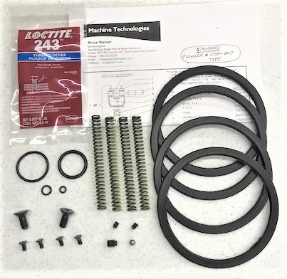
Also, In our Punch-Head Rebuild Kits we have Changed from a
Cup-Type Set-Screw to a Extended-Tip Set-Screw
as we found on some Machines the Cup-Type Set-Screw
did Not Push Ball into it's Seat Tight Enough
so then it would slowly Leak Oil.
The Extended-Tip Set-Screw Fixes this Rare Problem.
Punch-Head Rebuild Kit
is Shown Below.
Set Oil to Correct-Level at
Bottom-Dead-Center with #49579-000 Dip-Stick!