Broken Crankshafts
There were about 1300 Strippit CNC Turret Machines Built with Air Clutch & Brakes in the FC750, FC750/2, FC1000, FC1000/2, FC1000/3, 1000XT, FC1250/30/1500 Product Lines.
All of these Machines have a Problem. Their Nice-Thick (4" on FC1000's & FC1250's,
3" on FC750's) Crankshaft is Turned-Down to Only 2" where it Goes through Brake Assembly. This would probably be OK if Strippit had Machined a Nice-Round Radius at this Transition, But they Did Not do so. They all have a Sharp Transition from 4" (or 3") to the 2" Section. This Causes Stress Risers to Form at this Transition,
and it will Eventually Crack and Break if Crankshaft is Overstressed & Abused.
To Help Prevent Crankshaft Failures,
I Advise All my Customers to Properly Maintain Their Machines, and Especially To:
1 -- Keep their Clutch & Brake Systems in Good Working Condition, No Drag or "Fight"
2 -- Keep Good Clutch & Brake Solenoid Valves on Machine, Replace Sticking Valves!!!
3 -- Change Drive-Pully (Shive) to Reduce Press Speed RPM and System Stress!
4 -- Never -- Never -- Never "Pop" The Clutch Valve to get the Ram-Up!!!
One Thing I have Noticed about Good Advise, People Never Take it!
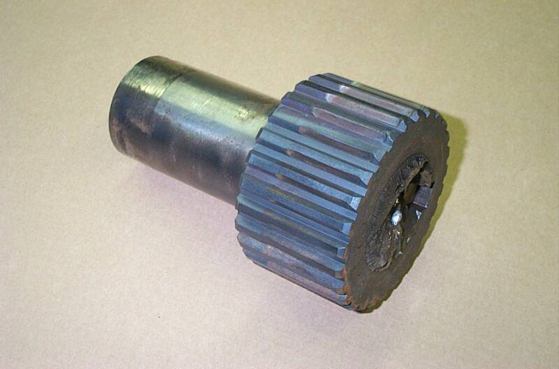
The Result is, I get Several Calls a Year from Shops when they
Break the End off their Crankshaft, Just like in Picture Below.
They are Now All Looking for a Quick & Easy Fix. There Isn't One.......
You now have 3 Choices;
1 -- Scrap your Machine, which seems a Bit Extreme.
2 -- Buy a New Crankshaft from Strippit, and Install it.
3 -- Repair Your Crankshaft, and Reinstall it.
Now, You would Think that Strippit would Happily Keep Crankshafts In-Stock, as they Charge $3000 to $4000 for them, and they are Just a Big Piece of Steel Bar-Stock Turned on a Lathe. But they Usually do Not have any, and have a Lead-Time of Weeks or Months, If they will Even Bother to Make One for you.
Understand Here, Strippit is in the "Selling New Machine Business",
Not the Repair / Parts / Service Business of Older Machines, Like Yours.
So, that Leaves Repairing your Crankshaft.
It's a Lot of Work, and your Machine is going to be Down for at Least Several Days,
so just take a Deep-Breath, and just get used to that Idea.
Note, If You had Taken my Advice Elsewhere on This Web Site,
and Purchased a Second Machine, You would Not be in a Production Bind Now!
If You had Purchased the Same Model Machine,
Not only would You Have Increased Production Capacity, But It would also give you Enhanced Troubleshooting Ability as you Could Swap CNC Control & Other Parts.
Don't Cry to Me that you Don't have Enough "Floor Space" or "It's Too Expensive",
I've heard All the Winy Excuses. Older Strippits are Cheap these Days and Do Not take up that much space. All Machines, New & Used, Break!
If it's Critical that you Can Punch Parts Everyday,
Then Just Find A Way, and have 2 Machines Up & Running, Side by Side!
I have Repaired 8 Machines with Broken Crankshafts,
and All have been Successful, with some Running OK for Over 10 Years Now.
These are My Guidelines, Not a Detailed Step-By-Step Procedure.
If You or Your Mechanic are Not Comfortable doing this Type of Heavy Repairs, and
Can't Figure-Out all the Many Unspoken Small Details, then Hire Someone Who Can.
The Following is How I do it.
CAUTION! CAUTION! CAUTION!
Eye-Bolts & Chains Can Break! Use Extreme Caution,
as you will be Handling Very Heavy Oily Steel Objects
that can Fall and Cause Crushing Injuries!!!
And You will be Working and Standing on Oily Machine,
where You Can Easily Slip & Fall and be Injured!
1 -- Remove all Sheetmetal Covers around Front of Machine.
2 -- Remove Brake Assembly & Timing-Hub & Sensors It can be Lifted off by Hand.
3 -- Remove Clutch. It weights about 150 lbs. I firmly attach a Heavy Chain to Tips of a Fork-Truck. Other end of Chain is lowered to Clutch. Using a Good-Quality 3/8" bolt,
bolt Last link in the Chain to a Holes in the Outer Diameter of Clutch Assembly.
Carefully, Just Take-Up Weight of the Clutch, Slide it off Crankshaft,
and lower it onto a Strong Steel Work Table.
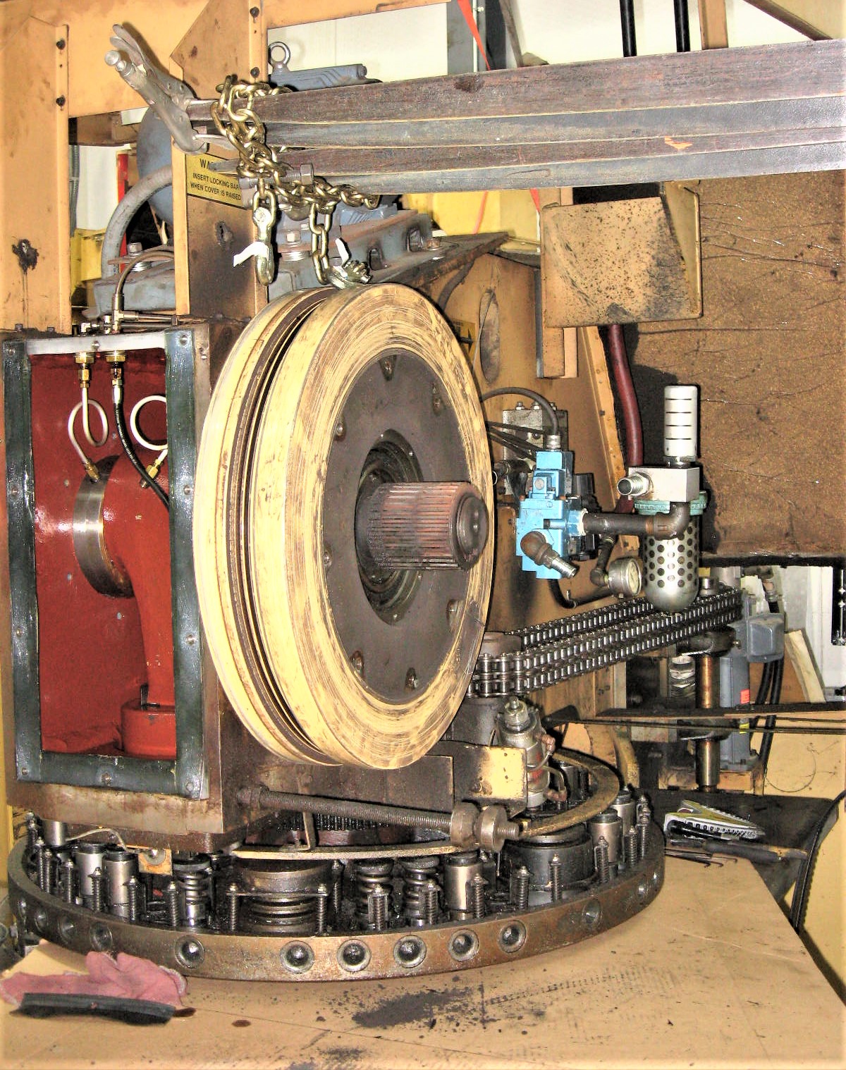
4 -- Remove Flywheel. It weights about 400 lbs. Use a Good Hardened Eyebolt
Screwed in to Tapped Hole that was Machined into Flywheel just for this purpose.
A Fellow Serviceman had a Eyebolt Break, allowing Flywheel to Drop to the Floor,
and almost Crushed His Foot! Never Get Under a Lifted Load!!!
This is One of those "Bad Things" that You Really Want to Try-Hard To Avoid!
Unbolt Bearing Retaining Ring. Attache Chain to the Flywheel, and Just Take-Up Weight
of it with the Fork-Truck. It will Slide-Off Quill fairly Easily, but you will need
2 Long Crowbars, 1 on each side of Flywheel to Start it Moving.
I then Lower Flywheel on its Edge, onto a Strong Steel Table so that I have access to Seals & Bearings on both sides. Put 2 pieces of 2x4 at the 2 ends, then Nail 2 more to them at Sides, to help prevent Flywheel from Rolling or Falling over.
White Rag is Covering Front Sheetmetal Support so I don't Cut My F'in Bald-Head on it.
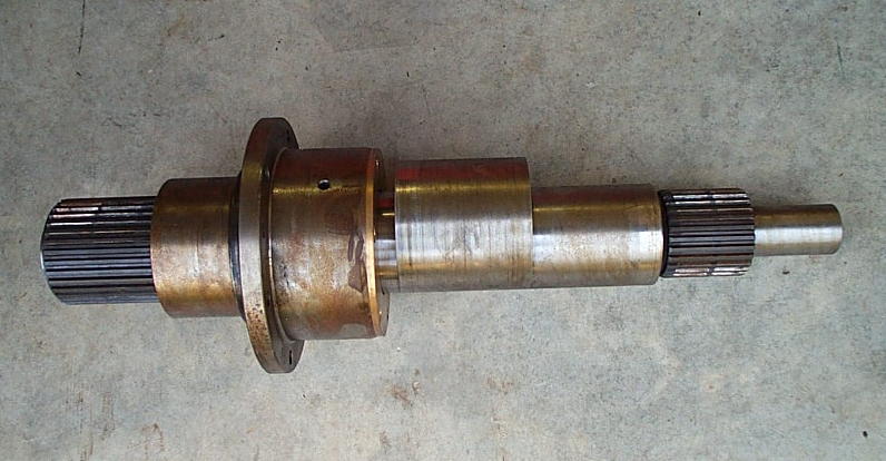
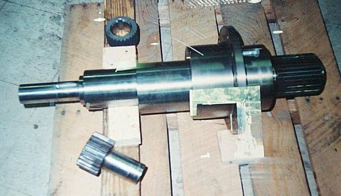
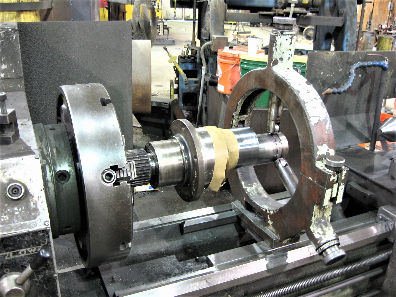
Above Photo is of a Good (Unbroken) FC1000/3 Crankshaft.
Clutch Splin-Hub is on Left,
Next is Clutch-Side Quill, with Crankshaft Support Bronze Bearing Inside.
Note, Because of Someone's Poor Engineering Work, you can Not pull Crankshaft out of Clutch-Side Bearing-Quill unless you Cut-Off Expensive Clutch Splin-Hub.
Crankshaft Eccentric is in Middle, which Drives Pitman and Punch-Ram.
Next is Brake-Side Crankshaft Bearing Journal, with-out Brake-Side Quill & Bearing.
Brake Splin-Hub is on the Right.
Aluminum Timing Disk Mounts on the Very Right-End.
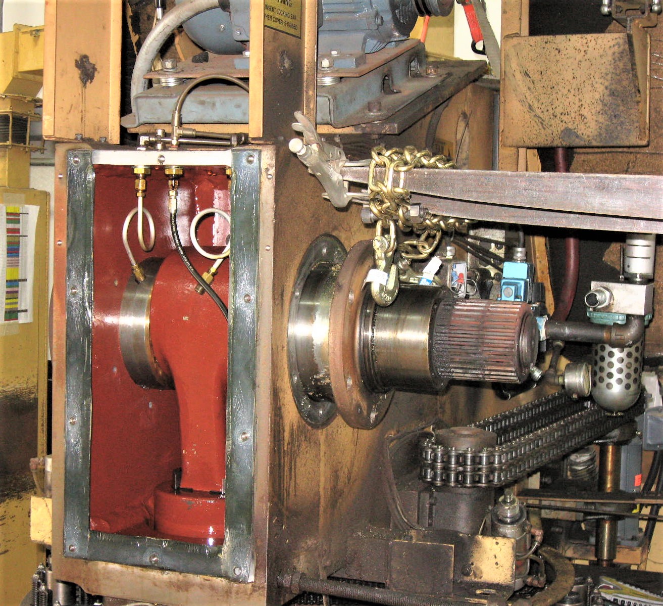
5 -- Unbolt Front Cover Plate, so that you can remove Lube Lines going to
Clutch Bearing Quill that supports that end of the Crankshaft.
6 -- Remove 6 Bolts holding the Clutch-Side Quill to Machine Frame. Quill is sealed to Frame with a "Sealastic" to prevent oil leaks. There are 2 Tapped holes in the Side of Quill, you can Screw 2 Bolts into these holes to force Quill away from Frame.
7 -- Bolt your Fork-Truck Chain to Clutch-Side Quill. Put Wood Blocks under Ram to Support it when Crankshaft is removed. With Workmen up on Machine Pushing & Guiding Crankshaft out, it should easily slide-out. Have Workmen Support the Brake-End as it comes out. Do Not let it Swing and Damage it's Bearing Journals!
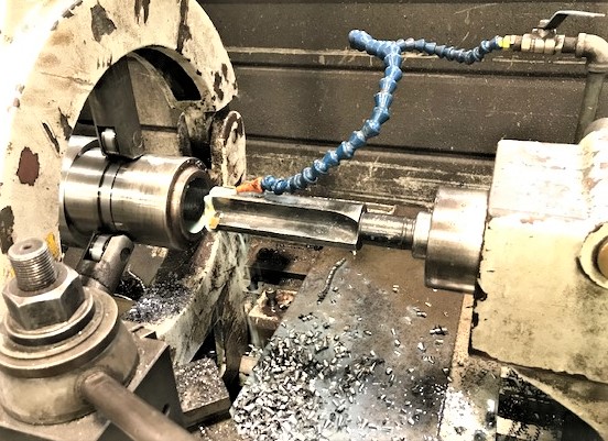
8 -- Now you need a Really Good Machinist and Machine Shop!
--- Wrap Bearing Journals with Electrical Tape to Help Protect them from Scratches.
--- Chuck Crankshaft into a Good Lathe with a Steady-Rest supporting Other-End!
--- Face-Off Broken End as best you can.
--- For the FC1000 & FC1250 4" Crankshafts, Bore a Hole 2.500" Wide x 3.000"
Deep, with Straight Sides and a Smooth Finish. Carefully Measure your Hole.
Make a New Stub-Shaft .004" Wider than Bored-Hole, 2.504" For Example.
Make the transition to the 2" Size Very Smooth so you get No Stress Risers!
Note, the Exact Hole Size is Not Really Important, Just that New Stub Shaft is
.004" Larger in Diameter, so that you end up with a Good Tight Interference Fit!
--- For FC750 3" Crankshafts, Bore a Hole 2.000" Wide x 3.000" Deep,
Make the Stub-Shaft .004" Wider than Hole, 2.004".
--- Use a Good Grade of Tool Steel. Strippit made their Crankshafts out of
"Maxel 3 1/2 RC 28-34" Steel, whatever that is.
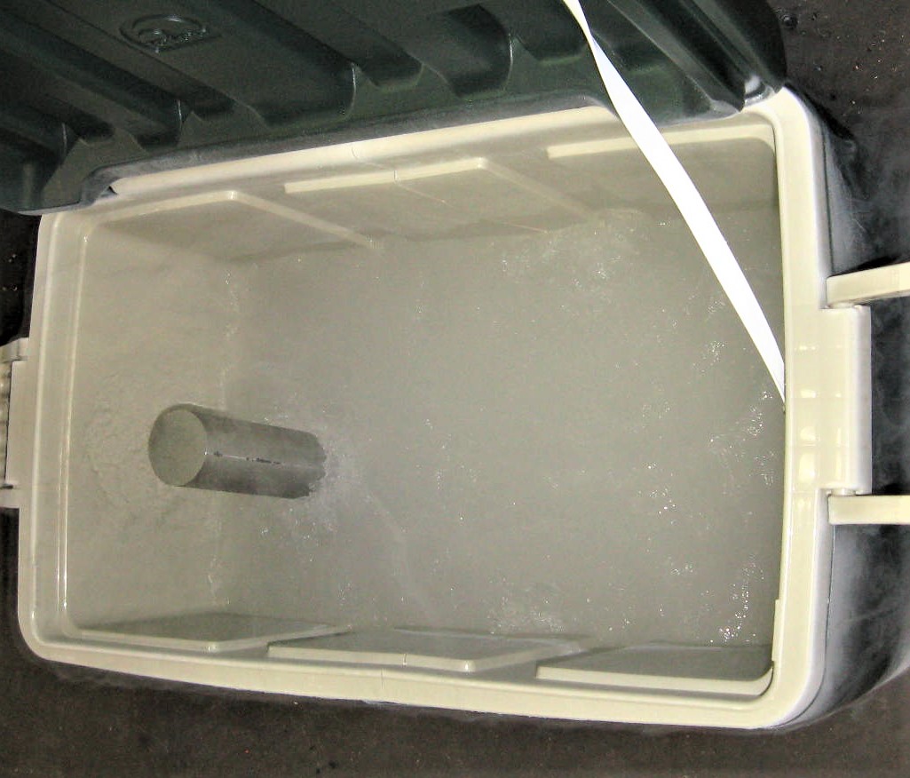
--- Obtain a few Gallons of Liquid Nitrogen from a Welding Gas Supplier. It comes
in a Dewar Tank, and you need a Hose attached to it. Carefully Release Liquid
Nitrogen into a Small Cooler set onto the Floor. There will be a Lot of Fog!
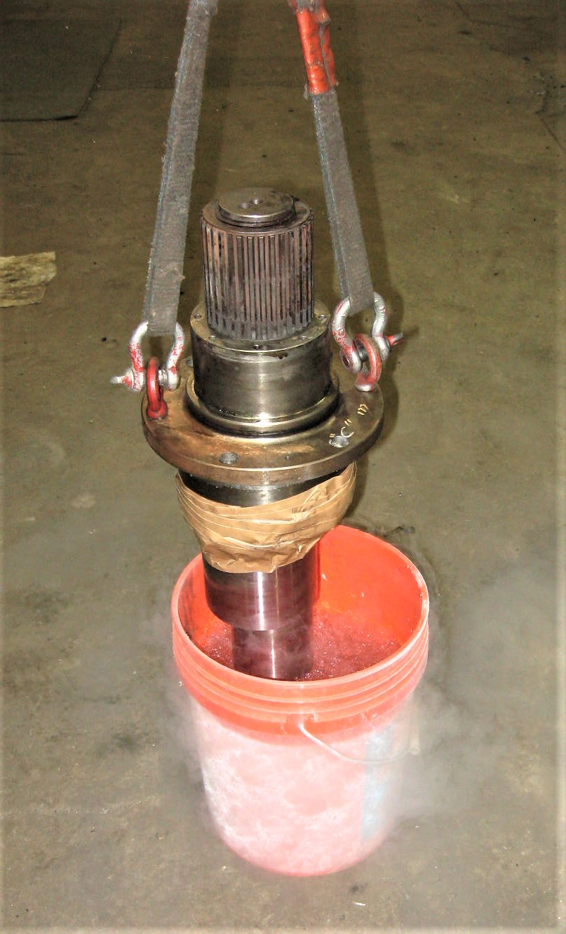
--- Immerse Stub-Shaft into Liquid Nitrogen to Shrink it, about 20 Minutes or so.
Stub-Shaft should Shrink about .008".
--- Crankshaft has to be Heated to about 200 degrees Fahrenheit to Expand Hole.
This should Expand the Bored-Hole about .003".
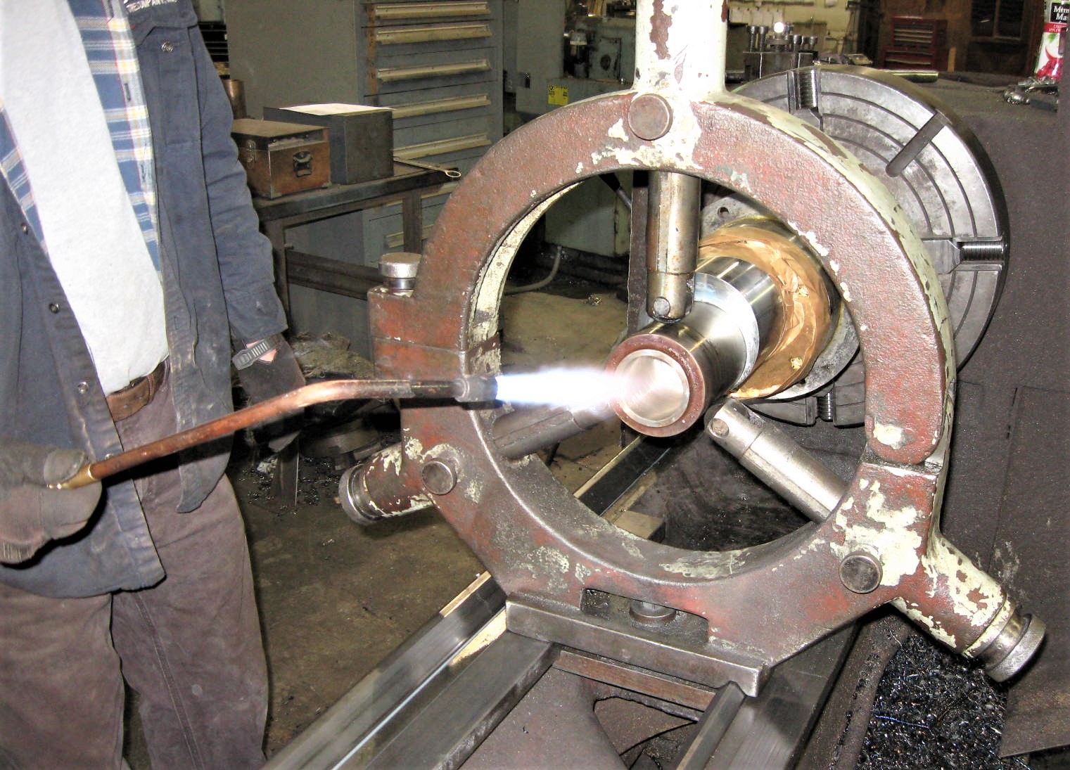
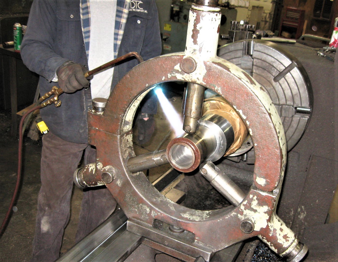
One Machine Shop put Crankshaft back in their Lathe and Very Carefully used
Acetylene Torch to Heat it. This held Crankshaft Firmly and worked very well.
You could also Lay the End of Crankshaft on a Electric Hot-Plate for a Couple of
Hours with a Tent of Sheetmetal over it, to Heat and Expand it, to help insure Stub
Shaft goes in all the Way for a Good Fit.
--- When Crankshaft is Hot, and Stub-Shaft is Cooled & No longer Bubbling,
Quickly Push It into your Bored Crankshaft Hole. Have a Small Hand Sledge
Hammer Handy & a Brass-Rod in case you need to Hammer-It Home a Bit!
--- Stub-Shaft will Rapidly (in Seconds!) Expand into a Tight Interference fit into
Crankshaft, So-Be-Quick! See More about obtaining a Good Interference Fit
--- Chuck Crankshaft back into the Lathe.
Machine New Stub-End to Match the Old Broken-Off End.
--- Machine a Smooth Radius to the Brake Spline-Hub Area.
--- Brake Spline-Hub Part of the Stub-Shaft is Machined-Down to
2.002" to 2.003", This Is Very Important, as the Brake Hub is Shrunk-On Here!
--- Mill In the Keyway Slot, and Snap-Ring Retaining Slot. We sometimes do not
do this, as if you do a Good job of Machining and Fitting, the Spline Hub will
Stay-Put OK Without a Key & Snap-Ring to Hold It.
But you are Surly Safer if you do Machine-In & Install Key and Snap-Ring.
--- Strippit Typically (But Not Always) Machined the Shaft in Front of Hub to
1.985" to 1.995". This was to make it a Little Easier to Slide-On the New
Hot (Expanded) Brake Spline-Hub, But is Not Really Necessary.
Some were made with the 2.0015 to 2.002" Diameter all the way to the End.
We like 2.0015 to 2.002 Shaft Diameter all the way to the End,
as it is Better to Fit Our Nylon Timing-Hub on to.
--- If you are going to use the Old Aluminum Timing Disk,
Machine End of the Shaft to Just like Your Old Shaft End.
--- If you want to use Nylon Timing-Hub & Prox-Sensor Retrofit like Ours, I Would Make
New Shaft 2" Longer, with the End Drilled & Tapped in Center for a 1/2" Bolt.
This Extra Length gives us More Room to Fit Nylon Timing-Hub and Sensor
Bracket at End of Shaft, and to have Clearance for Brake Movement.
--- Note! Your Machinist may Cry about not being able to Machine Crankshaft with
Clutch-Side Quill & Bearing Still-On. Too Bad, it Can Be Done,
as the Photos Below will Show, though it is certainly more Difficult!
He & You will have to Make Sure Inside-Surface of Quill and Surface of Crankshaft
Eccentric facings it, Does Not Rub or Gall or Wear against each other while being
Machined or Transported! These are "End-Bearing" Surfaces that control End-Play
on Crankshaft and Must Not Be Damaged!
On Other Side of Quill, Make sure Seal is Not Damaged by Hitting Clutch Spline Hub
or you will have an Large Oil Leak when its all put back together!
The Alterative is to Cut-off Clutch Spline-Hub so that you can remove Quill.
Then, of course, you have to Buy and Install a Expensive New Clutch Spline Hub on Crankshaft when Reinstalling into Machine. Your Choice.
This page was last updated: May 26, 2025
10 -- Coat All Metal Bearings Surfaces with Thin Coating of Mobil Grease.
Reinstall Crankshaft back into Machine.
-- Put a Bead of Silicone around Clutch Bearing Quill so Lube Oil does Not Leak.
-- Squeeze a Little Grease into 2 Flywheel Bearings, Not Too Much Though.
Too Much Grease will cause a Condition called "Churning" which will make
Grease get Too-Hot, and Burn, Leading to Bearing Failure. I use
Mobil Mobilith SHC 100 Synthetic Grease more Stabile than Regular Grease.
Also, Slowly Pour a Couple of Ounces of Mobil-1 10-30W Synthetic Motor Oil
into the Flywheel Bearing to help in re-lubing Bearings.
-- Coat Seals, and Metal Surfaces that Contact the Seals, with Grease.
-- Use Locktite 241 or an Equivalent Medium-Strength Thread-Locker,
on 6 Bearing Retainer Bolts and the 6 Quile Bearing Retainer Bolts.
Torque to 23 FT/LBS Max. Over-Torque can cause Bearing Failure!
-- Coat Clutch & Brake Splin Hubs, and Internal Splins Inside the Clutch &
Brake Assemblies, with Molykote GN Paste (The Same Paste You Should be
Using on Your Tooling!) as a Lubricant. Apply GN Paste with a Toothbrush.
-- Reinstall Clutch & Brake, Flywheel, Lube-Lines, Air Hoses, Timing Plate or Hub
(In Future, I may add Information on our Hub Retrofit), Etc.
-- Install New Mac Valves if Needed, Hoses, Belts, Etc.
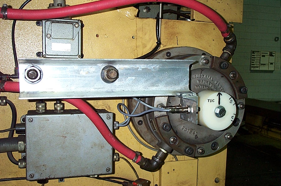
-- Set Clutch & Brake Air Pressures. Punch a few Times, and Reset Timing so that
on Normal-Punching, Crankshaft Stops just a Little Before the 12 O'clock Position
(Top Dead Center). Then when you are Contour-Nibbling, and Press Drive Builds
up More Momentum, Crankshaft will Stop a Little Past T.D.C..
This way, Stopping Point is Balanced between these 2 Conditions.
Caution! Caution! Caution!
Liquid Nitrogen is Minus 320 Degrees Fahrenheit!
It looks like Water, and is Fairly Easy to Handle.
But Much Care Needs to be Taken so that it is Not Splashed,
Not Touched, and NOT Ever Allowed to come in to Contact with Bare Skin,
As Instant Tissue Damage Will Result!!!
Wear a Long Sleeve Shop Coat, Long Leather Welding Glovers,
and Safety Goggles Over Your Eyes!
Use Long Channel-Lock Pliers to Handle Stub-Shaft in the Nitrogen.
=============================================================
We also Use Dry-Ice for Shrinking-On
Flywheel Bearings, Clutch & Brake Splin Hubs on to Crankshafts.
Dry-Ice is Solid Carbon-Dioxide, and is Minus 109 Degrees Fahrenheit!
Use All the Same Handling Cautions Listed Above,
like when using Liquid Nitrogen!
Machining & Assembly Prints would be Very Helpful in doing this whole Process!
Strippit Used to be Very Helpful in this Regard, but has become Quite Anal in Recent years. They usually Refuse to Provide Any Machine Prints At All, Service People have said they could be "Fired" if they do. How Pathetic, These Strippit "Staff" Policies.
It's One thing if they have the Part In-Stock, But if they Do Not, then they Should Gladly Sell You Prints for an Obsolete Part on a Obsolete Machine, and Keep You Happy and
In the Strippit Camp! And Not Drive You Away to Another Machine Brand.
They are Afraid that Myself and Others are going to Steal all their Business,
Which is So Silly. I have Helped Strippit Sell New & Used Machines,
and have Recommended them for Years.
But, Their Bad Attitude in Service & Management has Forced Me to Rethink This.
Strippit's Reputation & Image, as well as Machine Sales, could Only Improve if they would "Get It" and Work with All People & Companies again, like they did when they were #1 in the Industry. The Analogy here is the Superior Apple Macintosh, that was
a "Closed" System vs "Open" but Very Primitive IBM PC Personal Computer.
We all Know who Won The P.C. Computer Wars.
Anyway, Call them Up and Ask. The Prints that you Want Are;
FC750 and FC750/2 Machines;
#102268-000 Crankshaft Part Number & Machining Print
#103005-000 Press Drive Installation Prints, set of 2.
FC1000/1 and FC1000/2 Machines;
#100182-000 Crankshaft Part Number & Machining Print.
#100768-000 Press Drive Installation Print. How-To Info & Part Numbers, Very Helpful!
FC1000/3 Machines;
#104117-000 Crankshaft Part Number & Machining Print,
for Early Machines using Aluminum Timing-Disk
#105004-xxx Early Press Drive Install Prints, set of 2
#107365-000 Crankshaft Part Number & Machining Print,
for Later FC1000/3 Machines using Nylon Timing-Hub
#108004-000 Later Press Drive Install Prints, set of 2
#118909-000 Crankshaft Part Number & Machining Print,
for Hydraulic Clutch & Brake Machines
#118942-000 Hydraulic Press Drive Installation Prints, set of 3
FC1250/30/1500 Machines;
#101881-000 Crankshaft Part Number & Machining Print,
For Machines with 20-Station Turret using 1-Disk Brake Assembly
#101878-000 Press Drive Installation Prints, set of 2
# ? Crankshaft Part Number & Machining Print
For 33-Station Machines using 2-Disk Brake Assembly
# ? Press Drive Installation Prints
FC1000S, FC1000SX, FC1000SXP, FC1250S, FC1250SX, and FC1250SXP Machines;
#119783-000 Crankshaft Part Number & Machining Print
#130009-xxx Press Drive Installation Prints, set of 4
FC1250M Machine;
#119680-000 Crankshaft Part Number & Machining Print
#119638-000 Press Drive Installation Prints, set of 3
FC1250/45 Machine
#101342-000 Crankshaft Part Number & Machining Print
#101344-000 Press Drive Installation Prints, set of 2

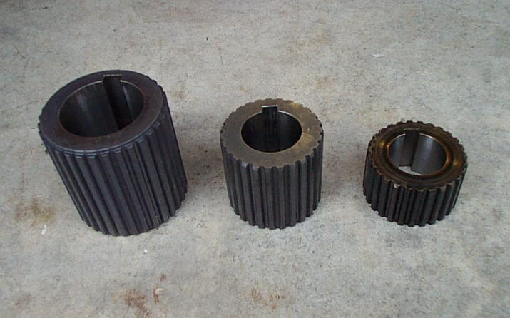
#18079-600 Clutch Spline Hub.
For All FC750, FC750/2, FC1000/1, FC1000/2, FC1000/3, FC1250/30/1500 Machines.
#18841-700 Brake Spline Hub For All 2-Disk Brake Machines,
Like s/n #38 and Up FC1000/3, and All 33-Station FC1250/30/1500 Machines.
#18075-600 Brake Spline Hub For All 1-Disk Brake Machines, Like the
FC750, FC750/2, FC1000/1, FC1000/2, and All 20-Station FC1250/30/1500 Machines.
Not Shown, But we also Stock the #18841-600 Ring-Feder Type Brake Spline Hub
that was used only on the Early s/n #1 to #37 FC1000/3 Machines.

Here Are The Spline Hubs That You Will Need.
We Have All These Hubs In-Stock!
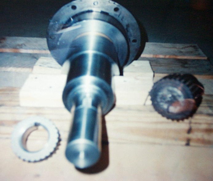
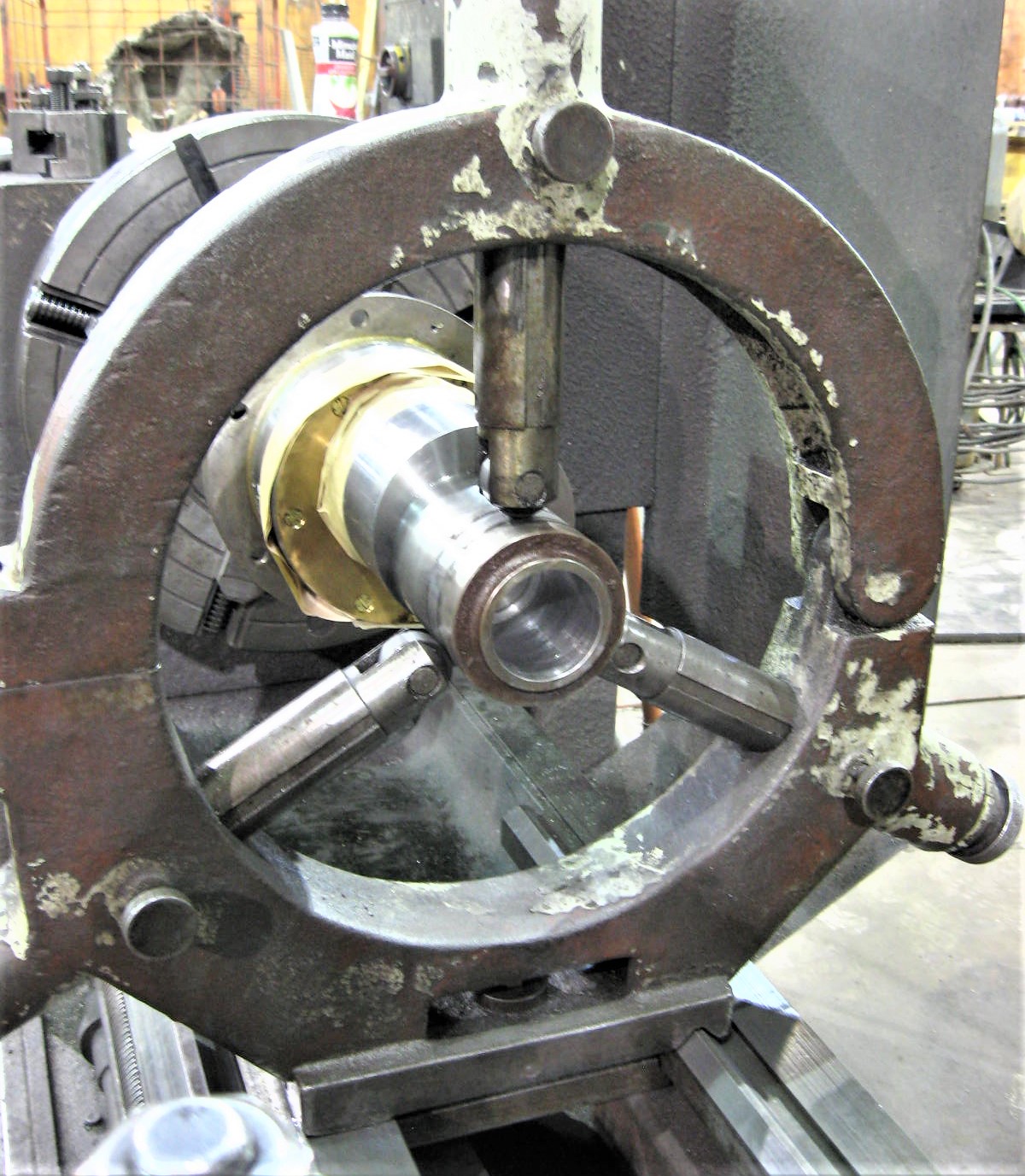
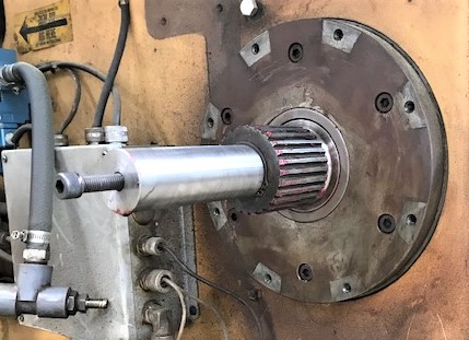
2 Photos of a
Repaired & Machined
Crankshaft
Ready for the
New Brake Splin Hub
to be Shrunk-On.
Notice,
This Work Can Be Done
with the
Clutch-Side Quill and Bearing Still Mounted On The Crankshaft!
This Crankshaft
Will Receive Our
Nylon Timing-Hub Retrofit.
9 -- Buy & Install a New Brake Spline Hub on End of Crankshaft. We Stock Spline Hubs!
Fit a New Key into Crankshaft Keyslot. Run a File All Over the New Key,
End of Crankshaft, and Inside of the Spline Hub to Make Sure that there are
No Burrs Anywhere that might Stop Hub from Sliding On Easily!
Slowly Heat Hub (To Expand it) to about 400 Degrees on a Hot-Plate.
We Set the Hub Between 2 Aluminum Plates to help Distribute Heat Evenly.
Use an Infrared Thermometer to Check Temperatures.
Take Your Time, and Do It Right! Takes about an 1 1/2 to 2 Hours.
At the same time, take a Cardboard Box, Fill it with Dry-Ice.
Cut a Hole in Side of Box, then Shove the End of Crankshaft in to it,
to Cool & Shrink the Brake-End of Crankshaft. Let it Cool for at Least an Hour also.
Put-On Heavy Welding Gloves. Pull Crankshaft out of Dry-Ice. Pick-Up Hot Hub
with Pliers, and with your Gloved Hands, Quickly Push Brake Spline Hub All the
Way on Crankshaft. Done Right, it should Slide-On So Loose, that it could Bounce
Back, so make sure it is all the way on! Have a Hand Sledge Hammer and a Brass
Rod Close-By, in case you have a Problem, and have to Drive it Home a little.
You Have to Work Quickly, as Hub will Shrink on to Shaft in Seconds!
Screw-Up, and you will have to Cut-Off Hub, get another New Hub, and try again!
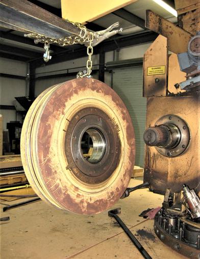
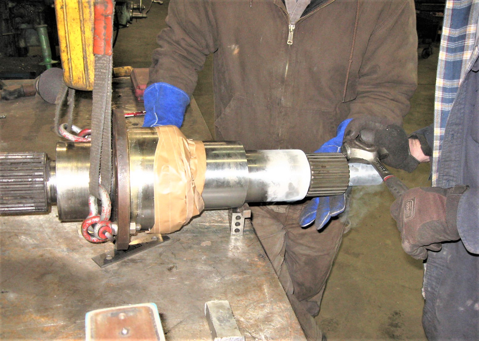
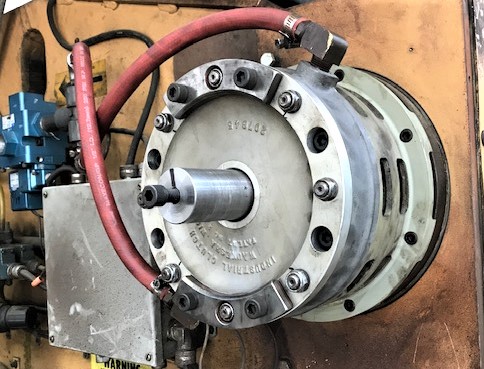
Above & Below are 2 Photos of a
20-Station FC1250/30/1500 Machine I Repaired.
This Machine has a Repaired Crankshaft.
Repaired Crankshaft was Lengthened 1 Inch, should have done 2 Inches,
to make it Easier to Mount Our Nylon Timing-Hub Retrofit.
New Bracket for the Clutch-Dump & Brake-On Prox Sensors
was Fabricated from Aluminum Channel.

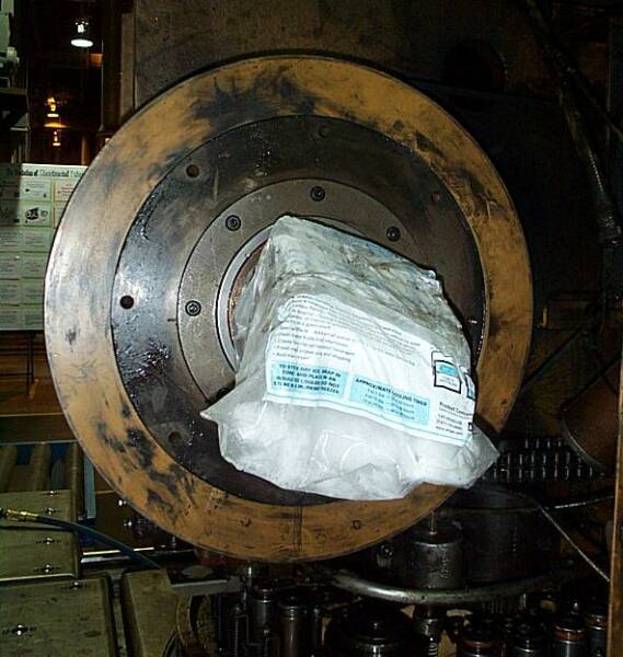
Chilling End of Crankshaft,
to Shrink-It,
before Sliding-On the
Heated & Expanded
New Clutch Spline Hub.
This is Just a Bag with
10 LBS of Dry-Ice in it,
Shoved over the
Crankshaft End,
with a few Wraps of Tape
to help hold it in place.
Let it Chill about a
1 1/2 to 2 Hours!
I use Same Technique
when Installing a
New Brake Spline Hub
on Machine.

Click-On Button to the Left
for More Related Bearing and Crankshaft Information!


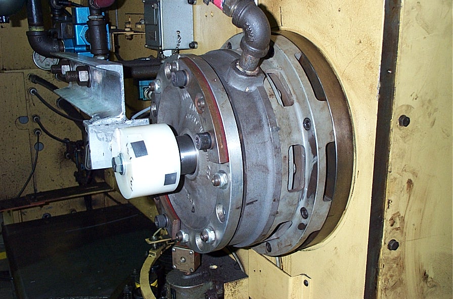
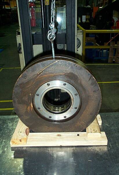
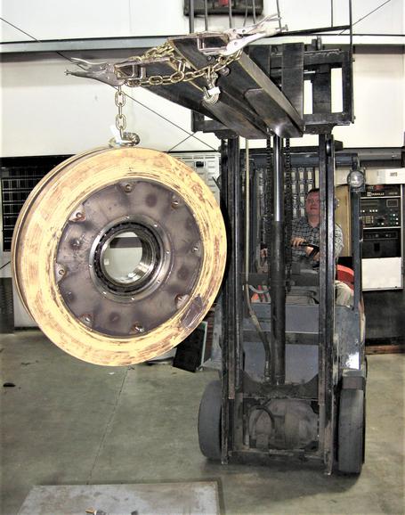
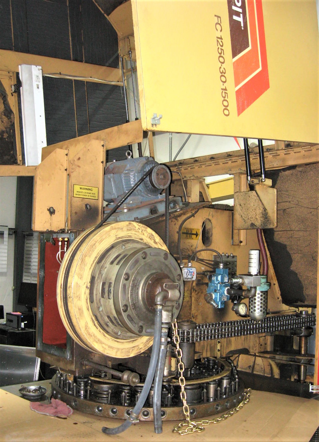
Below are More Photos of another
33-Station FC1250/30/1500 Machine I Recently Repaired.
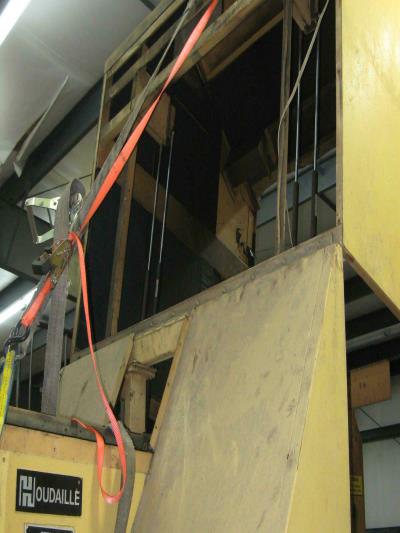
Above, Had to Flip Hood Back & Secure with Straps
to get enought Room to pull out Flywheel.
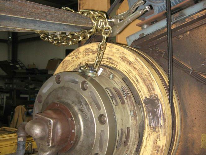
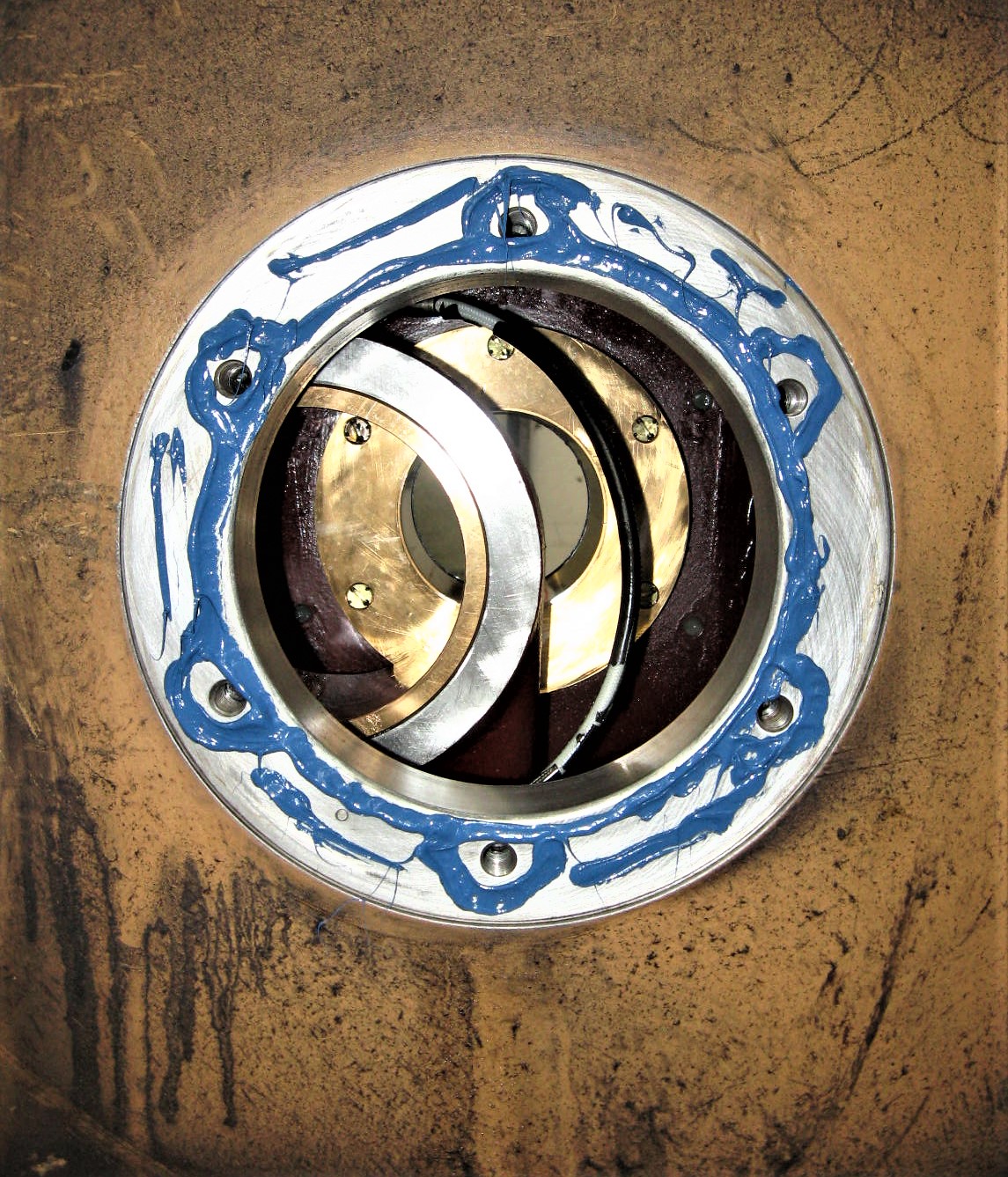
There is a Tapped-Hole
in Flywheel to
Bolt Lifting Chain to.
Un-Bolt Bearing Retainer
and
Carefully Slide the
Flywheel Off of the Quill.
!!! Caution !!!
NEVER get under the Flywheel
or any other Heavy Object
that could Fall & Cause Crushing Injuries !!!
Sometime I use 2 Crow-Bars
to get it moving
and Tap-It with a
4"x4" x 6-Foot Wood-Beam
as a Hammer.
Keep a "Jimmy" Handy to Do All "The Dirty Work"!
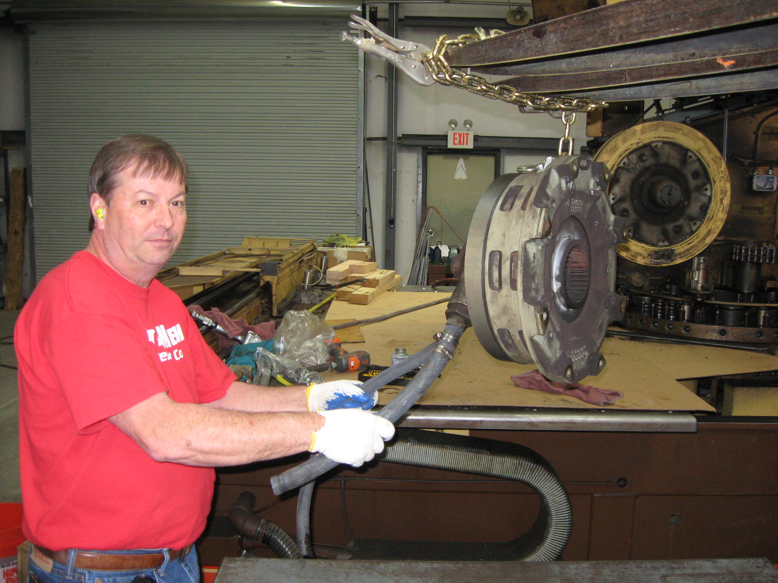
Un-Bolt Clutch, Slide it out a Bit, & bolt a Chain to to it. Wrap Chain around Fork-Lift Forks & Secure with Vice-Grips so chain does Not slide off!
Take the New Stub-Shaft
that you already made
and
put it into a
Liquid Nitrogen Bath
which will Shrink it down
about .008"
Un-Hook Lube-lines, Un-Bolt Clutch Quill, Wood Block-Up Ram. Slide Quill out
a Bit and bolt Chain to it. Slowly Back-Out Crankshaft with Someone up on
Table Holding & Guiding Other-End of Crankshaft out through the Frame.
Carefully Heat-Up End of Crankshaft to about 200 Degrees Fahrenheit
which will Expand Crankshaft Hole-Bore about .003"
A Good Machinist Dials-In the Crankshaft on a Big Lathe with a Steady-Rest.
Put Tape on Clutch Quill to keep it from Sliding Around.
Face-off Old Broken Surface and Bore-Out the End of Crankshaft.
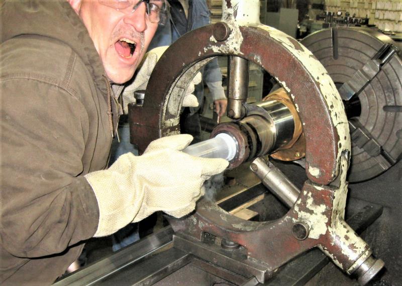
Stub-Shaft is Shrunk about .008" and Crankshaft Bore-Hole is Expanded about .003" giving you about .011" Total Clearance for your .004" Oversize Stub-Shaft.
So if you Measured and Machined Accurately, it will slide right in.
But have Heavy Hand Sledge-Hammer and Brass Rod Ready to Hammer it Home Quickly, Just in case. In this case, Stub-Shaft was loose going-in, as it should be, and he had to hold it in for a few seconds until it Expanded Tight into Bore.
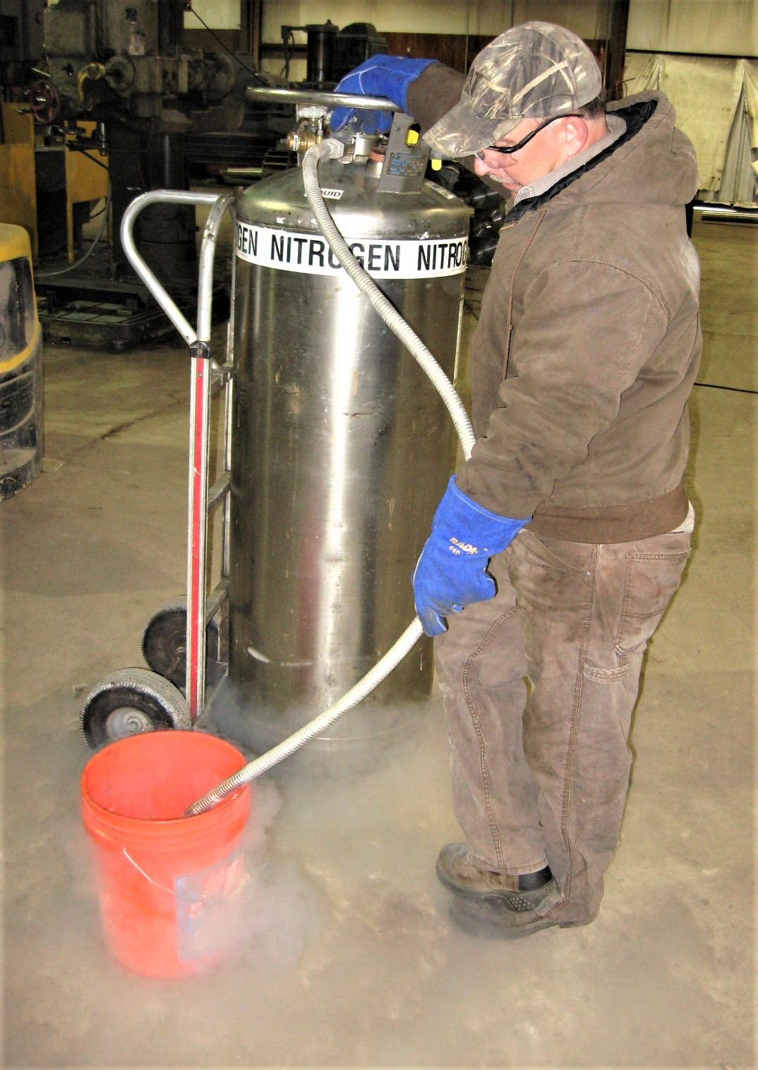
Now we put Liquid Nitrogen into a Bucket and Hang Stub-Shaft in it to Shrink it.
Brake Hub is Heated to Expand it.
I usually use a Hot-Plate
with a Piece of Aluminum Sheetmetal
Top & Bottom of Hub while it's Heating
but
Here we are using a
which is the Very Best Way
to Heat-Up the Hub
to about 400 Degrees.
Then Quickly Slide Hot Brake Hub over Cold Stub-Shaft and Hold it
into position until it Shrinks on to Shaft. Keep a Big Hammer & Brass Rod
Handy Just in case you have to Drive it Home if it's Too-Tight!
Use RV-Silicon Sealant as a Gasket where the Quill seats against the Frame.
Lube-Up the Bearing Surfaces & Seals. Check that All Seals are in Good Condition or Replace as necessary. I always replace the Brake Quile Seal.
I also replace both Flywheel Seals. With 1 Seal Replaced, I Lower Flywheel
down on that side, then Slowly Pour a Couple of Ounces of
Mobil-1 10-30W Synthetic Motor Oil into the Flywheel Bearing and
also Pack some Mobil MOBILITH SCH100 Synthetic Grease
around Inside & Surfaces of the Seals, there-by Re-Lubing Bearings.
Hang Crankshaft again with a Chain on Forks, but you will still need a
couple of big boys, on Table, to Help Guide it in.
Pitman has to be Aligned with Bore by Prying the Ram Up & Down.
Then you can Slide-On the Flywheel, BUT it must be Perfectly Aligned
or It Will NOT Slide-On! I usually get it Lined-Up & Push-it By-Hand
while Also Bumping-it with our 4" x 4" Wood-Beam that I'm using as a Hammer.
Once it starts-on, reduce tension on the Chain so it does not bind,
and Push it Home!
Repaired Crankshaft is now back in place.
Re-install, Flywheel, Brake, Clutch, Oil Lines, Timing Sensors.
Set the Clutch & brake Timing so that
Ram Stops at About 11:30 O-Clock Position
and you should be Back in Business.
New Hole for New Stub-Shaft was Cut-Out with Boreing-Bar using
Carbide Insertsthat were Carefully Set-Up for the Correct Dimentions.
Also, as the Brake Spline Hub was in Very Good Condition,
Machinest Carefully Bored-Out the Old Broken Shaft
Without Removing any Metal from Hub I.D.,
there-by Saving & Re-Using this Expensive Part, instead of Buying a New Hub.
I had this Stub-Shaft made 2" Longer than Original Crankshaft so I could Fit Nylon-Hub & 2 Prox-Sensor Retrofit, instead of the Aluminum Magnet Disk that Strippit used which causes so much trouble trying to keep it on the Crankshaft.
CAUTION! CAUTION! CAUTION!
Eye-Bolts & Chains Can Break! Use Extreme Caution,
as you will be Handling Very Heavy Oily Steel Objects
that can Fall and Cause Crushing Injuries!!!
And You will be Working and Standing on Oily Machine,
where You Can Easily Slip & Fall and be Injured!

Click-On Button
to the Left
for More Related Bearing and Crankshaft Information!