Common Strippit
CNC Turret Machine Problems
All Machines Have Problems. New Machines, as Well as Old Machines.
Machine Technologies Specializes in the
Strippit HECC80 CNC Control Turret Machines,
so I will show Some Common Problems & The Fixes for these Problems.
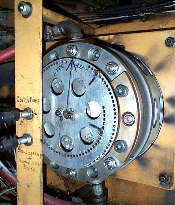
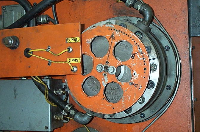
For many years, Strippit used a Aluminum Plate with 2
#17441-000 Magnets (3 on FC1000/3 & 33 Station FC1250/30/1500) for the Clutch & Brake Actuation Timing.
Different Model Machines had Magnets and #18122-000 Sensors in different Positions, but all work the same way.
At Top of Plate there was usually a Notch or Mark which indicated "Top Dead Center" (T.D.C.). At start of a Punch-Cycle, CNC Control would "Fire" both Clutch & Brake MAC Solenoid Valves at the same time. Brake would release, Clutch would Go-On, and Crankshaft would Rotate. As it Rotated, it would push Pitman & Ram downward to Punch-Tool.
As Crankshaft rotated 180 Degrees, Ram & Punch-Tool would now be at "Bottom Dead Center" (B.D.C) and must have Pierced Metal-Sheet Part, so "Clutch-Dump" Magnet now goes by it's Sensor, telling Control to Release Clutch. Clutch Releases, and Crankshaft & Ram starts Coasting.
About 30 to 50 Degrees later, "Brake-On" Magnet goes by
it's Sensor, telling Control to Release Brake.
Brake goes On, and the Crankshaft Brakes to a Halt.
If everything is adjusted Correctly and is in Good Condition (Clutch, Brake, Valves, Sensors, Etc.) Crankshaft should now be back at T.D.C. Position, ready for next Punch-Cycle.
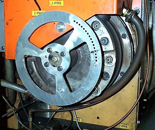
PROBLEM: Timing Plate getting Loose & Falling Off. This will also Damage Magnets & Sensors.
Because of Shock of Starting & Stopping millions of times, and Shock from Punching which travels up Ram to ends of the Crankshaft, causing Bolts Holding Timing-Plate to the Crankshaft get Loose, or even Break. There are 2 Things you can do to help this situation;
1 -- Lighten Disk by Milling or Laser out Holes in Disk to reduce MASS of the Disk, and therefor Shock-Load on Bolts. 3 Examples of Lightened-Disks are in Photos below.
2 -- Buy a Box of High-Strength bolts. As Preventive-Maintenance, every 3 Months or so, Replace
Old Bolts with New Bolts Before they Fatigue and Break! Make sure Old Bolts go into Scrap Bin, or
Someone will Reuse Them! Use a High-Strength (Hardened) Washer under each Bolt. Never use "Lock-Tight" or Thread-Locker Compound on Bolt-Threads, because when (Not if) they Break,
you will Never get them Out! A broken Bolt, Without Thread-Lock, can usually be "Walked-Out"
by Carefully Tapping Outer-Edge of Broken Bolt with a Sharpened Pin-Punch and Small Hammer.
Beautifully Done by
Custom Metal Fab Co.
of
Chesterfield, VA.
with their
Mighty Mazak Laser.
This Is
The Best Way
To Lighten
Your Timing Disk!
Timing-Disk is on
Their Strippit
FC1000/2 Machine
Timing-Disk
on a
Very Early Strippit FC1250/30/1500 Machine.
Holes are
a bit Crude,
but
still Effective.
Timing-Disk on a Strippit FC1000/3 Machine.
Nicely Done,
but
I would have made the
Holes Bigger
to make
Disk Lighter.
PROBLEMS: When Setting Clutch & Brake Sensors, Intermittent Ram-Downs,
Timing Magnets hit Sensors, Magnets Breaking and Sensors Damaged
This is usually cause by one of following causes;
1 -- The GAP between Magnet and Sensors are being Improperly Set.
Rotate Turret, and put a Empty Tool Station under the Ram. TURN OFF MACHINE!
Push-Down & Twist Pilot-Button on Brake Mac-Valve, this will Release the Brake. Grasp Timing
Disk with both hands, you should be able to rotate Crankshaft to align Magnet over its Sensor.
Check that Magnet is Perfectly Aligned, Left to Right, with its Sensor. If not, Adjust Sensor,
Bracket, Elongate the Mounting Holes, or whatever you have to do, to get Alignment Perfect.
Push & Pull Hard ON the Disk, you will probably feel and hear a small "Clunking" sound, this is Crankshaft going Back & Forth because of "Slop" in the End-Bearings in your Press-Drive.
On some Machines Sensors are "Inside" the Disk, on other Machines Sensors are "Outside" of Disk. Push (or Pull) to Take-Up Slop between the Magnet & Sensor GAP.
Now, Set GAP to .025 Inch. Repeat this Alignment Procedure with the Other Magnet & Sensor.
In this way, Crankshaft can only Drift-Away From Sensors, and Not into it causing a "Crash".
Also, Do Not Over Tighten Nut on Magnet-Stud, it will pull threaded-stud out of the Magnet.
2 -- Wear in the End-Bearings is Excessive. Crankshaft will "Float" back & forth while Punching, causing Magnet & Sensor Crashes, or the Gap-Setting will get Too-Wide so that Sensors will Not Work at all, and you get a Intermittent "Ram-Down".
This Wear is usually caused by You, The Customer, NOT using Correct Lubrication Oil.
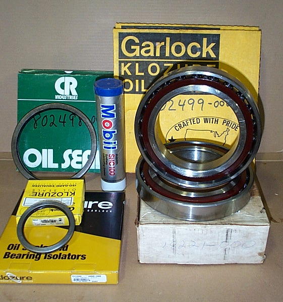
The Correct Lube Oil is MOBIL DTE "HEAVY" ISO 100 WEIGHT LUBRICATION OIL !!!
I Think SAE 30 WT Motor Oil is also OK. If you have Doubt, Change your Lube Oil & Filter!
Most Customers & Machine Operators are Lazy and do Not Bother to read Excellent Manuals
that Strippit Produced (look at other Company's Manuals if you don't think so!).
And so they just Grab the First Bucket of Oil-Like Substance that they see,
after Machine Stops Punching with a "Lube" All-Hold Condition.
Often the First Bucket of Fluid they See is Hydraulic Oil, that all shops have Laying Around.
Hydraulic Oil is a Very Thin (ISO 32) Fluid Designed for Transmitting Power, NOT Lubrication!
They they fill the Empty Lube Tank with it, and Continue to Run Machine.
Over Time, This Causes Crankshaft Bearings to Grind themselves to Dust, causing the End-Play!
NEVER, NEVER, NEVER Use Hydraulic Oil In The Lube Tank !!!
It Is Very Difficult & Very Expensive To Replace Crankshaft Bearings.
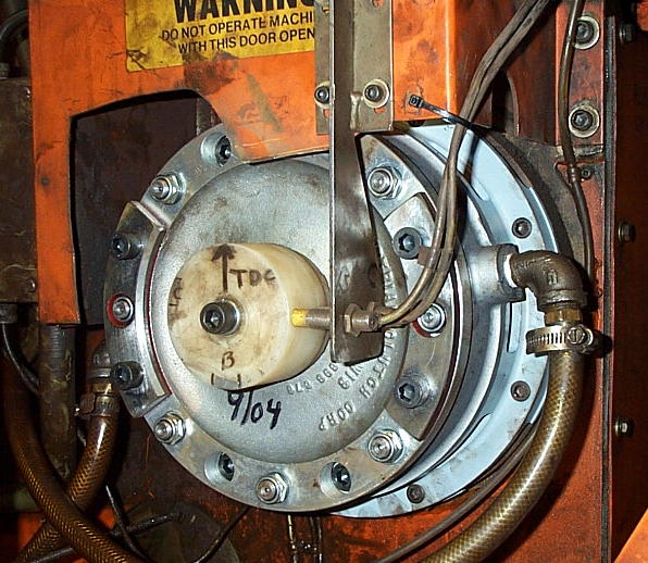
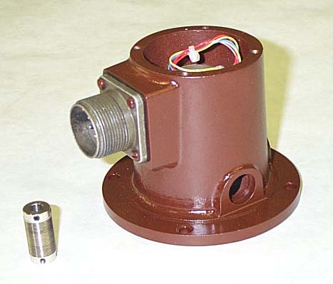
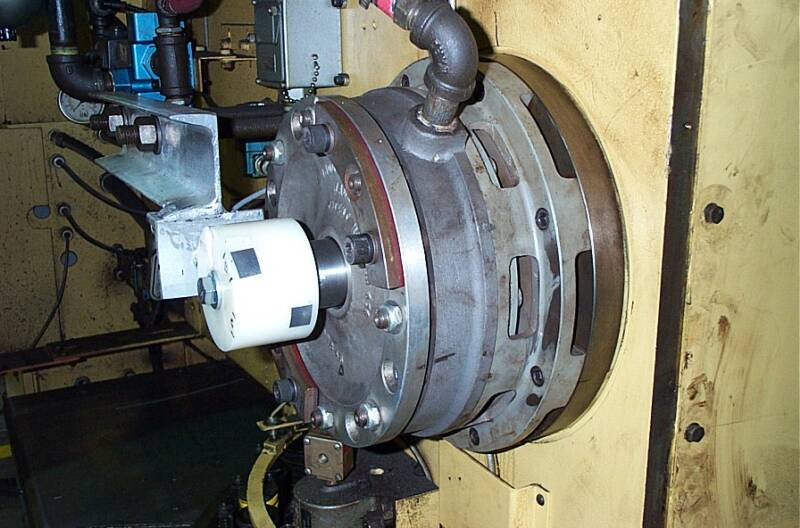
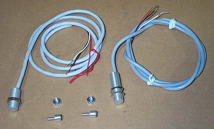
On these Machines we Retrofit a New Nylon-Timing Hub, New Bracket, and New Proximity Sensors in place of old Aluminum Disk & Magnet Sensors. Sensors are mounted at Side of Hub, and "Sense" the Metal-Foil Tape Patches that are placed on Hub. This way, Crankshaft & Hub can "Walk" back and forth, and does Not cause Magnet & Sensor "Crashes" of the Original System.
Starting in 1985, Strippit Quit using Aluminum-Timing Plate and Magnet Sensors for Press-Timing, and Switched to the Nylon-Hub with Metal-Tape for most of it's Mechanical Press-Drive Machines.

Our Nylon-Hub and
Prox-Sensor Retrofit on a
Strippit
FC1000/2 Machine.
Note,
We also fit this
Machine with
Latest-Style
Stroke-Limiter
Brake Assembly,
which Lasts-Longer
and
Works-Better
than Older-Type
Original Brake
that
Strippit used.
PROBLEM: Machine Stops with a "RAM DOWN" Error Message.
A Common Problem with MANY Different Causes. As it is a Press-Drive System with Many
Components (Clutch, Brake, Valves, Regulators, Sensors, Electronics, Etc.) Troubleshooting
is Difficult as Anything in The-System that is Not Correct can Cause Same Ram-Down Symptom.
1 -- Make sure it really has a True Ram-Down Condition, and Not a False Error caused
by a Miss-Adjusted or Damaged "Ram-Up" Sensor or Control I/O-Input Problem.
2 -- Look for Clues! Did it Stop when making Hi-Tonnage Punch? Sometimes Shock and
Vibration will Rattle "Door-Open" or other Switch causing "All-Hold" or "Punch Hold"
Condition which will cause Control to "Kill" Punch-Cycle Immediately wherever it is.
3 -- Make sure "Clutch-Dump" and "Brake-On" Sensors are Not Damaged and are
set-up properly. Check Magnets or Sensor-Tape Patches that actuate Sensors.
See "Setting Clutch & Brake Sensors" Section below.
4 -- Make sure Timing-Hub or Timing-Disk is Tight, and does Not have Broken-Bolts
which allow it to Slip Timing Position.
5 -- A Bad-Lube Signal will Kill the Punch-Cycle. Check Lube Tank Level, Pump, Lube-Sensors,
and Lube Oil Type. HECC80 CNC Controls want to see a Lube-Signal, from Lube-Block
Switch, Every 2.5 Seconds or Less or it Will Issue a "Bad Lube" Signal which will Flash
up onto Self-Scan Display, but this Message will NOT-Latch and will Disappear if Condition
is intermittent! Control also issues a "Punch Hold" which will Stop Punch-Cycle wherever
it happens to be. Usual cause is a Worn-Out Lube-Pump, Wrong Too-Thick Lube Oil,
Too-Cold Lube Oil, or Faulty Sensor Assembly on Lube-Block. We Stock Replacement
Pumps, Filters, & Sensors. Note Machines with Fanuc Controls work Somewhat Differently!
6 -- Check Air Pressures. Low Air Pressure will cause "Work Clamp Open" Errors which
Kills Punch-Cycle. I like Air to Machine 100 to 110 PSI, Fed from a 1" Pipe, with
Regulator set to 95PSI. Make sure Air Filters are Not Clogged with No Air-Restrictions!
7 -- Air Gages are Commonly Bad, Replace with Hi-Quality Glycerin-Filled Gages.
8 -- Check Clutch and Brake air Pressures. Clutch & Brake Regulators sometimes go Bad
causing Slow Air-Flow. In U.S., I Replace with New #4ZM09 3/4" or 1" Hi-Flow
Regulators from Grainger Co. or other Good Brand. Plumbing changes may be required.
I Set Clutch Pressure to 55 LBS, NO Higher!!!
On Single-Disk Brake Machines (FC750, FC750/2, FC1000/1, FC1000/2,
20-Station Turret FC1250/30/1500, and FC1250/45)
Set Brake Air Pressure to 55 LBS, NO Higher!!!
On 2--Disk Brake Machines (FC1000/3 and FC1250/30/1500 with 33-Station Turrets)
Set Brake Air Pressure to 38 to 40 LBS, NO Higher!!!
Do NOT Increase Brake Air Pressure! It Makes Brakes Work Slower!
9 -- Make sure Drive Belts are in Good Condition and are Tight.
10 -- Check Clutch "Poppit" Valve, which is Inside Clutch QRV-Rotary Seal Assembly.
Poppits Break and Crumble with Age & Do Need Replacement Periodically!
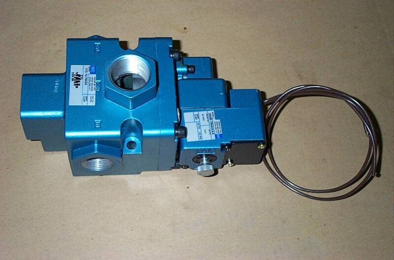
#18085-000 Standard 8.5-Watt Valve for Air Clutch & Brake Usage
on Most Machines.
We Custom-Order
Our Valves with
Special Internal-Seals
to Reduce Sticking Problems
and with
External-Actuator to make Troubleshooting Much Easier.
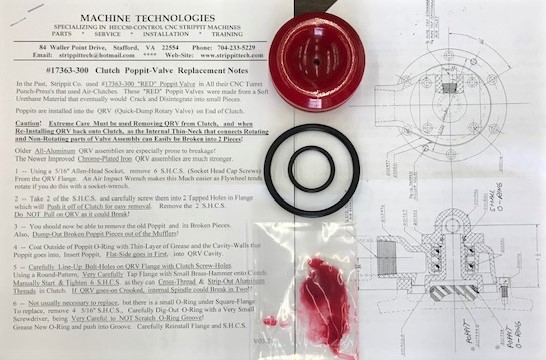
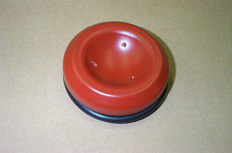
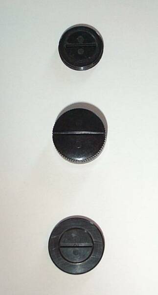
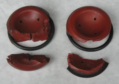
#17363-300 Clutch Poppit Valve
Original "Dull Orange-Red" Type
with 3 Holes. Clutch Poppits Crack & Fall-Apart (See 2 Photos Below)
as they Age, Causing Big Clutch
Air-Leaks & Loss of Punching Tonnage
& MUST be Replaced from Time to Time!
We Keep New Poppits Kits In-Stock!
Poppits Also Sometimes use Part Number 30003057 or 207444
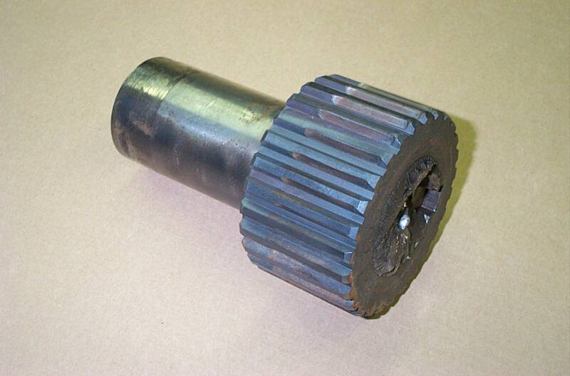
Above is Photo of The Brake-End of a Crankshaft Broken Off!
This Is One of Those "BAD THINGS" That Is Best Avoided!
Caused by Sticking Clutch & Brake Valves,
And by Stupid Operators that "POP" Clutch Mac Valve to get the "Ram Back Up"!
Never, Never, Never Do That!!!
To Get The Ram Up;
First, Make Sure Shotpins are In, Workclamps are Closed, You have Good (Above 90PSI) Air Pressure, and Anything Else that could Stop a Punch Cycle, is Fixed.
Then, Do a "Forced-Punch Cycle", Which is a Feature that Strippit Designed-In to
All Their HECC80 Controls to Force Ram to Cycle Back Up to Top-Dead-Center.
To Do "Forced-Punch Cycle" FOR HECC80/1 TYPE CONTROLS;
Push "Clear All" Button, and Wait a few Seconds for the Control to Reboot.
Put Lower Selector Switch in the "Tape" Mode.
You then put Control in "Auto" with the Upper Selector Switch.
Then Hold-Down "Cycle-Stop" And The "Punch" Buttons at the Same Time.
Ram should Cycle Up & Down until you Release One of the Buttons,
then Stops at Top-Dead-Center Position, Unless Something is Mechanically Wrong.
To Do "Forced-Punch Cycle" FOR HECC80/3 TYPE CONTROLS;
Select any Part-Program in Memory. Select the "Auto" Mode.
There should now be a "Force" Softkey showing on CRT Monitor.
Push it, and Ram should Cycle Up & Down until Released, and then Stop at T.D.C.,
Unless there is Something Mechanically Wrong that needs to be Repaired.
To Do "Forced-Punch Cycle" FOR GN6 CONTROL FC1000/3;
Set Mode Selector Switch to "JOG".
Press "Cycle-Start" AND "Manual-Punch" Buttons at the Same-Time.
Ram should Cycle and Stop at T.D.C. (Top-Dead-Center) when Switches are Released.
This should also work on GN6 Control FC1250/30/1500 Machines.
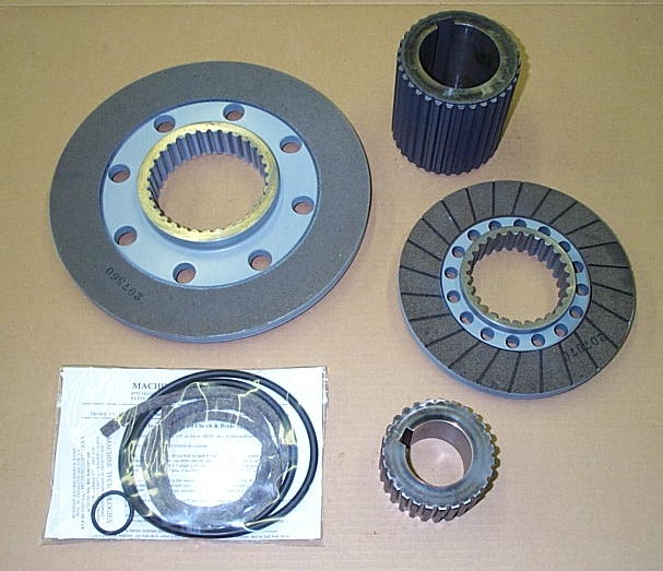
We Have Many Clutch and Brake Rebuild Parts
In-Stock!
There is More Brake Rebuilding Notes on Our
"Machine Repair Parts" Web-Page.
Clutch & Brake Parts have become Hard To Get, with a 4 Month Lead Time! Order Before Your Clutch & Brake is Worn-Out !!!
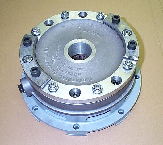
A New Brake Assembly
with Stroke-Limiter Option.
Brake & Clutche Assemblies & Repair Parts are Hard to keep
In-Stock, with a 4 Month Leadtime!
If you Need a New Brake or Clutch,
Order-It NOW Before Yours goes Completely Bad, as you may NOT be able to get one if You Wait to
the last Minute to Order!
14 -- Old FC1000/1, FC1000/2, and FC1250/30/1500 Machines sometimes had a "Quick-Dump"
Valve between Mac Air Valve and Brake. These were added to some Machines to try to
improve Brake Speed. They Do Not Work, and Actually cause Nothing but Problems!
Take It Off, And Throw It Away!
15 -- Older Machines Air Hoses go from Brake Mac Valve, to nearest side air-port of Brake, then
looped from this side over to air-port on other side of Brake. This caused air to rush in & out
one side of Brake, and caused Disk to Bind-Up & Wear Unevenly inside Brake Assembly.
We Replumb Brake As Follows;
--- Fit a 3/4" Short Pipe out of Brake Mac Valve
--- Fit a 3/4" T on the end of it
--- Add 3/4" to 1/2" Reducer Bushings to each end of T
--- Add 1/2" Hose-Barbs to each Bushing
--- Add 2 Equal-Length 1/2" Air-Hoses to the 2 Brake Air-Ports.
Air goes in & out equally out of Both Sides of Brake and Friction Disk does Not Tilt & Bind.
Brake Stops Better and Lasts Longer.
13 -- Rebuild Brake and Clutch Assemblies. Friction Disks become Worn, Seals Leak, Splin-Hubs
on Crankshaft become Worn, Etc. By a Factory Error, Most Brake Assemblies built in 1980's
used Wrong Friction Disks made of a Very Hard Ceramic Material that is Harder than Steel &
Iron used in Pressure Plates & Drive-Rings that they Push-Against. Over time, these Parts
become Very Worn & Grooved, along with Drive-Studs and other Parts, making it difficult or
uneconomical to Rebuild Brake Assemblies. We discovered this Error and our Disks have
Correct "Softer" Linings that don't Eat-Up the Metal Surfaces!
Clutches can usually be Rebuilt, but Brake action is Critical and it is often Better & Cheaper to
Replace with New Brake Assembly. Our Brakes are Latest-Types with Stroke-Limiter Option,
which Improves Brake Operation Speed, Improves Brake Life, and is Quieter.
Sticking Valves not only Cause Ram-Downs, but also other Punching Problems like
"Clutch & Brake Fight" which is when BOTH Valves are on at the SAME TIME!
This causes Tremendous Clutch & Brake Wear, but can also
BREAK Your Press-Drive Crankshaft! Do Not Ignore Sticking Valves, Replace Them!
To Check Poppit-Valve, With the Machine Off & Flywheel NOT Turning,
Manually Depress the Actuator on Clutch MAC Valve to put Air into Clutch.
Strippit used Recessed Actuators which means you will need a small Screwdriver to push it in. Valves Bought from Machine Technologies have a External-Actuator which is Much Easier to Use.
Clutch should Engage (Disks Bang-In!) Strongly and Hold-In with Little or No Air Leaking Out!
If Air is Rushing-Out around the Muffler, it is probably a Bad Poppit Valve.
If Air is Rushing-Out around Outside Diameter of Clutch, it is probably Bad Clutch Seals.
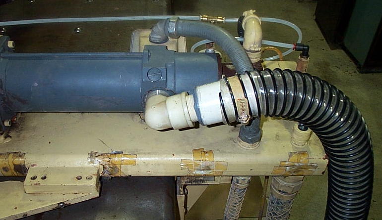
11 -- Make sure Air Mufflers are Not Clogged or causing Restrictions.
On FC1000/3 Machines, I take the 2 Tan-Color Filters Elements Out of Each of the
2 Reclassifiers on the Brake & Clutch Exhausts, as I have found them to Cause Valve
Actuation Problems, which makes Slow & Erratic & Intermittent Clutch & Brake Operation.
Throw the 4 Elements Away!!!
Or Someone will put them Back-In, and your Problem will Resurface in the Future!
12 -- Replace BOTH the Clutch AND the Brake Mac Valves!!! These Are Very Critical !!!
This is a Leading Cause of Ram-Downs, and is where I Start my Troubleshooting!
Sticking-Valves also Causes "Start-Up" Problems where you Punch & Clear Ram-Downs
a few time until it will Punch OK. This Condition will Break Your Crankshaft Sooner or Later!
Strippit Repair Parts & Strippit Service
Machine Technologies Co.
Phone 704-233-5229
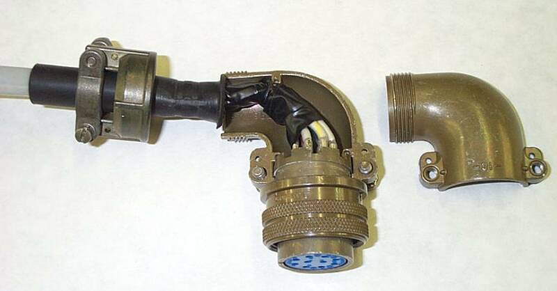
#17441-000 Magnets
and
#18122-000 Sensors
Used for Brake-On,
Clutch-Dump,
Ram-Up, and
Tool-Door Sensing
are No longer Manufactured, So Availability is Limited!
See Sensor Retrofit!
Flywheel Bearings
We Recently had 1 of our Good Customers Call Us, and Say
"Our Flywheel Is Coming Off The Machine!"
We Told them that their Flywheel Bearings were Bad for Several Years, But they Just Would Not Change them! Finally, Bearings Seized-Up, and Sheared All Retaining Ring Bolts, allowing Flywheel & Clutch to Walk-Off the Crankshaft! The only thing Keeping it on was Prog-Move Air Cylinder, which was Rapidly being Eaten-Up by the Flywheel.
We Repaired this Machine, But the Repairs were Much More Extensive, and Expensive, than if they had let us Repair Machine Before Bearings Failed Completely!
If your Flywheel Bearings are making a Loud "Roaring" Noise, and "Rumbles", and the Frame "Vibrates" as it Coasts to a Stop, Your Bearings are Bad! Replace Them!
We can put together a Parts-Kit with the Proper Seals, Bearings, Shim, Grease, and Instructions on how we Repair this Problem.
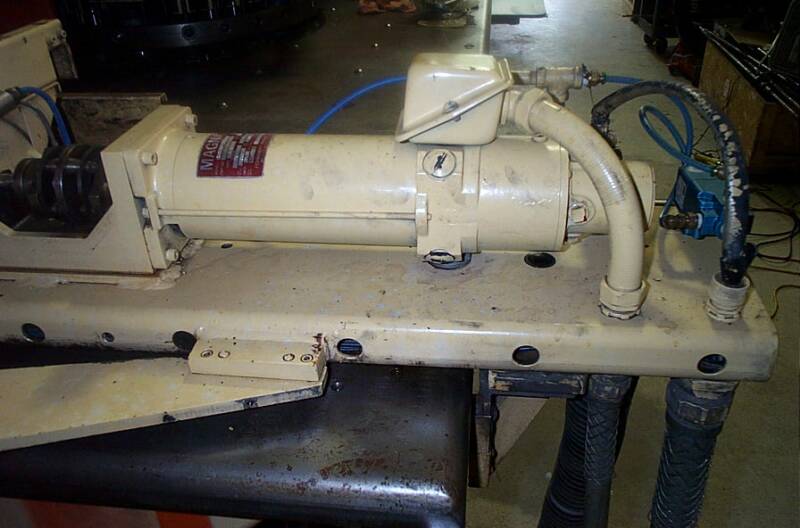
FC750 X-Axis Servo Motor Failures
When I Started "Tech Support" at Strippit, 1 Task I performed was Analyzing Machine Failures. I noticed a lot of X-Axis Servo Motors (#17497-000) were Failing on FC750 Machines. This seemed Very Odd, as Exact Same Servo Motor & Servo Drive was used on Larger & Heavier FC1000/2 Machine. But FC1000/2 Machines did Not Fail X-Servo Motors anywhere near the Hi-Rate that FC750's did. I talked to Engineering about this Problem, Their Solution was to Switch to Same Physical Size FC1000/3 T-Axis Motor (#19463-000) that would Bolt Right-In to FC750's X-Axis. But this did Not Solve Problem!
Cause was quite Simple. A simple Engineering Design Flaw on this Model Machine.
Y-Axis Carriage, which holds Complete X-Axis Assembly, is made from a 2"x10"x7' long Obround Steel Pipe. Air-Hose from Servo-Blower is Plumbed into Bottom of Pipe to Pressurize it. A 1 1/4" Hole is Bored into Top of Pipe right under Air-Input Port on
X-Motor, with a Rubber-Foam "Donut" squeezed between them to Seal Air-Flow.
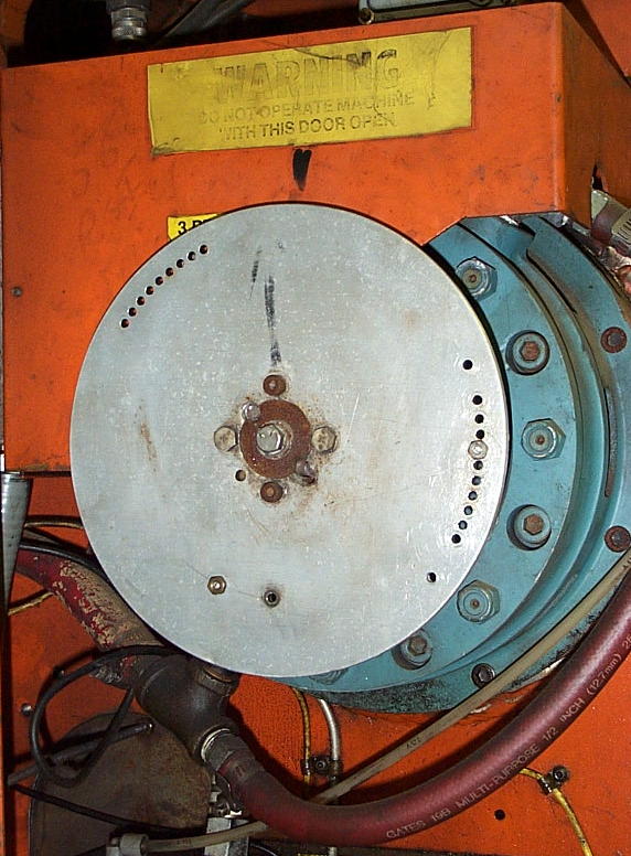
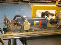
2 Problems. Carriage Pipe Is Full Of Holes, and Both Ends are Open! Look at Line of
1-Inch Holes in First Picture below. There Is No Air-Pressure to Feed the Servo Motor!
Strippit & Customers would Stuff Rubber Foam or Tape-Up Holes, but would Soon Rot
& Melt away from Oil & Time. And "Donut" Gasket under Motor would also Rot Away. Then Motor would Overheat, Armature would Melt, and Magnets would Delaminate
from Magnet-Shell. And You Got to Buy a New Servo Motor!
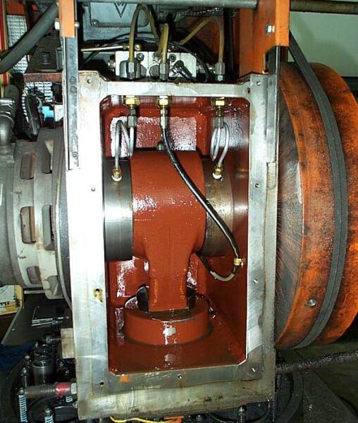
End of a Original FC750 Y-Axis Carriage with
X-Servo Motor
Mounted to it.
Notice all the 1 Inch
Holes Bored into it!
Ends of Y-Carriage
Pipe are Open Too!
No Cooling
Air Pressure to Motor!
What The Fuck
was Strippit Thinking?
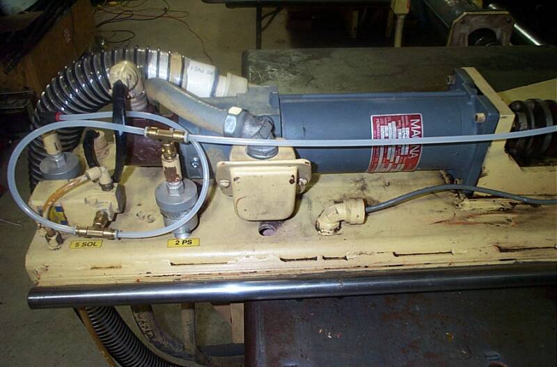
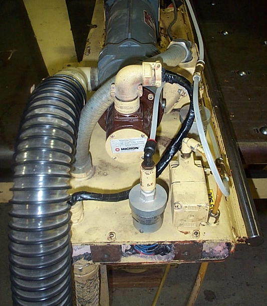
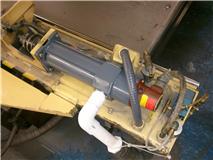
Below are 3 Pictures on how I Modified my FC750 to Fix This Problem Once and for all!
Idea is to Plumb Air-Hose Directly into the Motor's Air-Input Port,
like it was done on Most other Strippit Machines, such as FC1000/2 Machines.
1 - Remove Air-Switch, as it will be in the way of the Wire-Box on Side of Motor.
2 - Unwire Motor. Unbolt Motor-End of the Coupling. Remove Motor, and
Rotate it 90 Degrees so that the Air-Input Port is Facing Front of the Machine.
3 - Bolt Motor Back to the Mount. Bolt up the Coupling.
4 - Rotate Resolver Feedback Package so the Cable can be easily attached.
5 - Make a New Flex Conduit about 4.5 inches longer that old Conduit.
There should be enough slack to pull Motor wires through New longer Conduit.
Reinstall Conduit and Motor wires to the Wire-Box on side of Motor.
6 - Drill a New mounting hole at end of Carriage, where it is convenient to Mount
and Reattach the Air-Switch Wires.
7 - A 1.25" Plastic Street-Elbow was screwed into the Air-Port of Motor. Then a
Threaded 1.25" Plastic Pipe was screwed into Elbow. A 1.5" Plastic Pipe was
Epoxied over it. New 2.5" Flex Air Hose was Attached over it with a hose clamp.
8 - Replumb your Air Switches, and you should be back in Business. We now have a
VERY Strong Air-Flow coming out of Front of Motor, and Motor stays Cold!
9 - Note, your Axis Cover will no longer fit, unless you make a cutout for it.
It is actually better to leave Cover Off Machine so you can do proper Oiling of
Ballscrew and Thomson Bars, and you can now easily Inspect all the Axis and
No-Punch Switches for Proper Operation. Inspect them Regularly!
In These 5 Photos of 2 FC750's Machines, The-Cure for Overheating FC750 X-Motors!
It took me about 4 Hours of Work per Machine.
Not as Elegant as I would like, But I had to Work With the Original Design.
But it is a Good Permanent Fix for the Original Strippit Crappy Miss-Design.
X-Servo Motors Now Run-Cold on these Machines!
Preventing Servo Motor Failures
1 -- Heat is Major cause of Motor Failures, Check that Servo Blower Fan is Running.
2 -- Check that Air Filter is Not Plugged-Up with Dirt, they Usually Are! Replace it!
3 -- Check that Air Hoses are Not Rotted-Out and Leaking Air.
4 -- Feel that Strong Air-Flow is coming out of X & Y Motors. T is usually not cooled.
5 -- A Stuck-Punch or a Slug Pop-Up can Jam & Stalled-Out a Motor, which can then
Burn-Out in a Minute or 2 if Machine Operator does Not Shut-Off Machine and
Correct Quickly! Good Punch & Die Tooling is Critical! Improper Length & Height
Adjustments, Dull Punch & Dies, Wrong Die Clearances will All Cause Punch
Stripping and Slug-Pop-Up Problems, which lead to Many other Problems.
6 -- Axis Slow-Down and Limit Switches that are Not-Working or are Misadjusted,
can allow a Incorrect Part-Program or Operator-Command to cause Axis to Hit it's
End-of-Travel, and Stall & Burn-Out Motor like the above Condition.
I have seen Shops try to run Bigger-Sheets by Defeating these Switches, these
same Shops then Wonder why they Break Ballscrews, Burn-Out Motors, Etc.
7 -- Check and Replace Motor Brushes Before they Wear-Out and Ruin Commutator.
8 -- Servo Motors are Relatively Fragile. Make sure that Guard-Rails are installed
around Machine so that Work Tables and Lift-Trucks do Not Hit and Break Motors.
When Shipping Motors, pack in bubble-wrap & strong boxes to Prevent Damage.
Ignore Above Recommendations at YOUR Peril !
Servo Motor Brush Types
A Great way to Ruin your Servo Motors, is to Never Check Brushes for Wear,
and to Not Install New Brushes when they are Worn-Out.
We Can Rebuild Your Old Servo Motors, and We Stock Rebuilt Servo Motors for
Those Shops that Do Not Change Motor Brushes!
I Recommend Checking X and T Axis Motor Brushes every 12 Months,
and Checking the Y-Axis Motor Brushes every 6 Months.
Replace Brushes when Half the Length is Worn-Off.
Do Not let them get Too Short, or You Risk Ruining your Expensive Servo Motor!
If Brushes seem to be Wearing-Out Too Fast, Check more Often,
as perhaps Commutator is Worn, and is Wearing-Out Brushes Too-Fast.
If Commutator is Worn, Motor will Need to be Rebuilt to Fix this Problem.
All CNC HECC80 Control Strippit Machines used following 3 Types of Motor Brush.
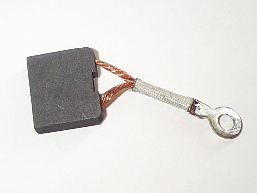
#17506-000 "Small Brush"
.25" Thick x .5" Wide x .626" Long
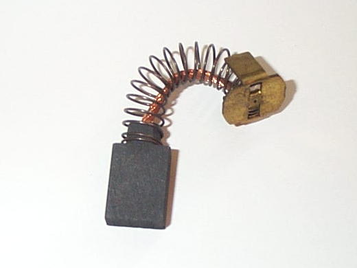
#17788-000 "Large Brush"
.25" Thick x .75" Wide x .75" Long
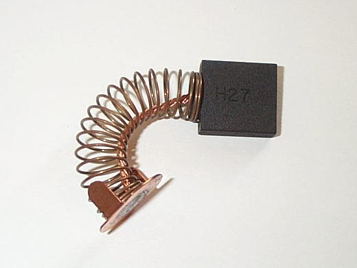
#19463-100 Special Type "C" Brush,
used for All HECC80 Control FC1000/3 Machines, and some FC1500/45 Machines.
.25" Thick x 1.0" Wide x .875" Long
The Following is a Servo-Motor and Brush Usage Chart
for NC & CNC HECC80 Control Strippit Machines;
FC750 & FC750/2 Machines
X- Axis uses #17497-000 Motor using 4 - #17506-000 Brushes
Y- Axis uses #17360-000 Motor using 6 - #17788-000 Brushes
FC1000/1 & FC1000/2 Machines
X - Axis uses #17497-000 Motor using 4 - #17506-000 Brushes
Y - Axis uses #17360-000 Motor using 6 - #17788-000 Brushes
T - Axis uses #17539-000 Motor using 4 - #17506-000 Brushes
FC1230/30/1500 & FC1250/30/1500 LaserTool
X - Axis uses #17538-000 Motor using 6 - #17788-000 Brushes
Y - Axis uses #17360-000 Motor using 6 - #17788-000 Brushes
T - Axis with 20-Station Turret uses #17539-000 Motor using 4 - #17506-000 Brushes
T - Axis with 33-Station Turret uses #19463-000 Motor using 4 - #19463-100 Brushes
FC1250/45, FC1250/45/72, FC1250/30, FC51/30, FC51/40
X - Axis uses #17538-000 Motor using 6 - #17788-000 Brushes
Y - Axis uses #17360-000 Motor using 6 - #17788-000 Brushes
T - Axis uses #17510-000 Motor using 8 - #17506-000 Brushes
FC1000/3 HECC80 Control, Not Fanuc Control FC1000/3
X - Axis uses #19462-000 Motor using 4 - #19463-100 Brushes
Y - Axis uses #19399-000 Motor using 4 - #19463-100 Brushes
T - Axis uses #19463-000 Motor using 4 - #19463-100 Brushes
FC1500/45
X - Axis uses #19800-000 Motor using 4 - #19463-100 Brushes
Y - Axis uses #800162-000 Motor using 4 - #19463-100 Brushes
T - Axis uses #17510-000 Motor using 8 - #17506-000 Brushes
Note, Many FC750, FC750/2, FC1000/1, and FC1000/2 Machines have FC1000/3
#19463-000 T-Axis Motor Installed on X-Axis in a Attempt to Increase Reliability.
These Motors are easy to Identify, as Brush-Covers are a Steel-Rectangle Cover,
and Not Normal Round-Plastic Cover. These Motors use 4 -- #19463-100 Brushes.
Machine Technologies Stocks these 3 Motor Brush Types,
3 Round Plastic Brush-Covers, & All Listed Servo Motors above.
Servo Motor Brush-Caps
Brush Caps are Easily Chipped and Broken by Careless Removal with a Screwdriver.
Make a Tool out of Thin Sheetmetal that Fits your Brush-Caps to Avoid Breakage.
"Small-Disk" Type Brush Caps that are used
with Most New-Style Motors that use the
"Small" #17506-000 Brushes.
3/4" Wide with Threads on the Outer-Diameter
"Small-Cup" Type Brush Caps that are used
with an Old-Style Motor that use the "Small" #17506-000 Brushes. Cup-Shaped, 13/16" Wide
with Threads on the Inner-Diameter of the Cup.
"Large-Disk" Type Brush Caps that are used
with Most Motors that use the "Large"
#17788-000 Brushes.
7/8" Wide with Threads on the Outer-Diameter

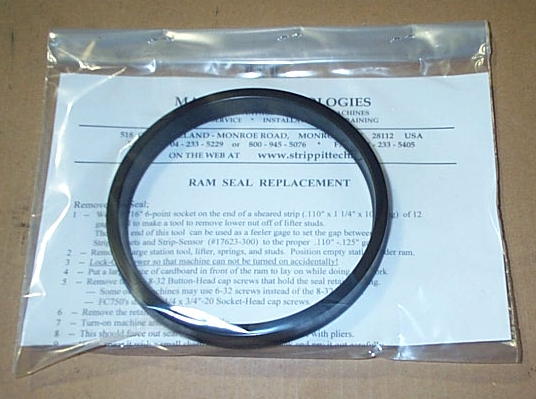
Ram-Seal Replacement
If your Machine has Mechanical Press-Drive (Flywheel & Crankshaft) and is Leaking Lube Oil
around Punch-Ram onto Tooling & Upper Turret, you probably need a New Ram-Seal. As
Seals Age, they become Brittle & Crack or Break into Pieces, allowing Lube Oil to Leak-Out.
Ram-Seal is not real hard to replace, but it will take several hours. You have to remove several Tool Lifters to get room to work under Ram, Remove the Retaining-Ring and Seal, Carefully Jack-In New Seal using Different Length Screws & Retaining-Ring, all Done while Laying on a Piece of Cardboard up on Machine's Tables in Front of the Ram.
We Stock a Kit with the New Ram-Seal, New Socket-Head Cap Screws, and Instructions.
For the 30-Ton Machines like FC1000/1, FC1000/2, FC1000/3, FC1000S, FC1000SXP, FC1250S, FC1250SXP, FC1250/30/1500, & FC1250/45 Series, Order Part #17534-000.
For FC750 & FC750/2 Machines, Order Part #18224-000. We Stock Both of these Seals!
Press Drive Lube System
A "Bad Lube" Error Message on Control Display is usually the first Indication Something is wrong with Lube System. This will then cause a "Punch Hold" Condition, and if it happens during Punching, will stop the Punch-Cycle Immediately, causing a "Ram Down" Condition.
The "Bad Lube" Error Message is Caused by HECC80 Control Not "Seeing" Lube Sensor Switch Open & Close every 2.5 Seconds.
The older Strippit Machines with Mechanical Press Drive Systems used a Pressurized Lube System to Supply Lube Oil to Crankshaft & Pitmen Bearings, and to Punch-Ram. System is Quite Reliable, I have Machines that have run over 40 Years with No Problems at all.
But sometimes they do Break, Requiring Parts and Service.
System consists of a 5-Gallon Lube-Oil Tank with a 1/4HP (Early Systems) or 1/3HP Motor turning a Special Oil Pump with a Built-In Relief-Valve. Oil is Pumped through a Filter, with a Pressure Gage on each side of Filter so you can Monitor Pressure Differential to see if Filter is Clogged. Oil then Travels to a Metering Distribution Block, which Cycles Oil to 1 Bearing at a time. A Magnet-Rod is attached to 1 of the Metering Pistons, and travels Back & Forth as the Block Cycles. This Magnet Actuates an External Switch that Signals to CNC Control that Lube System must be Working as Block is Cycling. Oil then travels through Aluminum Lines to each Bearing. Oil works its way out the side of Bearing and falls to Bottom of Sump below Crankshaft, then Gravity Feeds through a Return Line back to the Lube Tank.
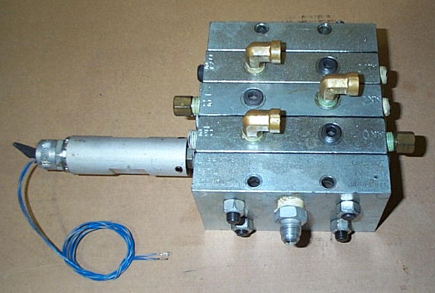
Lube-Oil
Metering
Distribution
Block with
Original Type
#17955-100
External Switch
There are a Number of Failures that can affect this Lube System;
1 -- See if Electric Motor is Turning. Some Machine have a Fuse, and Some have a Fuse and a Overload Relay, Check Both. Motors also Fail, Easy to get a new one at Grainger Co.
2 -- See if there is Pressure at Gages. If No Pressure Pump has probably Failed. There is a Small Pet-Cock Valve behind Pump, open it and Air & Oil Foam will probably Bubble-Out indicating Pump has Failed. Failed Pumps Suck-Air and can Not Pump Oil. Pump can Not be Repaired, Replace it! Original Old-Type 1.5" Long-Shaft Pump is No longer Manufactured.
New-Type 1"-Shaft Replacement Pump Requires Extension-Coupling to reach Pump-Motor.
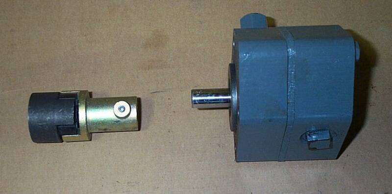
New-Type
#18722-200
Lube Pump has
Short 1.0" Shaft
and Requires
#18722-400 Special
Extension-Coupling!
We Stock
Both of these Parts!
3 -- When Replacing Pump make Sure that Motor & Pump Shafts are Perfectly Aligned in All
Planes! If Not Properly Aligned, Pump & Motor will Shake & Vibrate Violently,
which will Rapidly Ruin New Pump, and you will have to Replace it Again!
4 -- Make sure 2 Pressure Gages are Good. Original Gages are Cheap, Needles Fall-Off,
and are generally Untrustworthy. I replace them with New Glycerin Filled 1000 PSI Gages.
5 -- If the First Gage had a High Pressure Reading and Second Gage had a Low Reading,
that would Indicate that Filter was Plugged-Up, Replace it.
#17596-100 Lube Filter
Yeah,
We Stock
These
Lube Filters
also!
6 -- Make Sure Lube Tank has Correct Oil in it! Strippit Specs
"Mobil DTE "Heavy" Lube Oil", which is a ISO 100 WT. Lubrication Oil. I also use
and is easy to order in U.S. with UPS delivering to your Door.
I also use Straight SAE 30WT Motor Oil which works Good and Is Cheap & Easy to get!
Never, Never, Never, Use Hydraulic Oil,
which is used to Transmit Power, NOT to Lubricate!!!
Hydraulic Oil will allow your Machine Bearings to be Ground-Up into Metal Dust!
If in Doubt, Replace All Oil in Tank, and Replace the Filter!
Best to fill Lube Tank Monday Morning BEFORE you Turn-On Machine! This allows all Oil
to Drain back to Tank for a True Fill Reading. If you Fill Tank at other times, there is a Gallon or
so of Oil up in the Sump of Machine, and it will Drain Down Overnight, Tank will Overflow, and
there will be a Huge Oil Slick on your Shop Floor when you come in the Next Morning!
7 -- Lube System does Not Work-On or Require any Particular Oil Pressure. "Normal" is for Pressure to Oscillate Back & Forth between a Low of about 30-60 PSI to High of about 100-200
PSI every 1 to 2 Seconds. This Pressure Oscillation comes from Lube-Block Cycling through
it's Different Oil Chambers to the Different Machine Bearings, and is Completely Normal.
If you have 600 PSI on your Gages with No Oscillation, your Lube Block has Jammed-Up with
a Bit of Dirt or Trash. Oil from Pump Can Not get to Bearings as Lube-Block is Not Cycling,
so Pressure Builds until 600 PSI is Reached. Then Internal Bypass Valve Built-In to Pump
Opens-Up, and Routes Excess Oil back to Tank, Maintaining 600 PSI Pressure to
Lube Block until Problem is Repaired or Hell Freezes Over. SEND-IN to Us to Fix the Block!
8 -- Lube-Block is a Precision Built Assembly with Small Pistons that are Honed & Fitted &
Matched to a Cylinder in Each Section of the Block, with Interconnecting Oil Passageways.
Any Repair Attempts must be Done Very Very Carefully, or you will Never get it to Work Again!
I use a Part Washer Machine that Circulates Filtered Wash Fluid through a Scrub Brush.
I Wash all Dirt & Grime off the Outside of the Block. I then Carefully take 1 Section apart at a time, and wash all its parts Clean. I then Polish the Piston with a Scotch-Bright Pad, wash it again, then Coat it with Clean Oil, and reassemble that Block Section. Repeat with the rest
of Block Sections, then reassemble Block, and reinstall it back on Machine.
This usually restores Correct Block-Cycling, if not, Repeat this whole Procedure again.
9 -- Each time Lube-Block Cycles, Magnet inside it's Tube Moves Back & Forth with the
Piston it's attached to, causing External Switch Outside the Magnet-Tube to Open & Close.
If CNC Control Does Not "See" this Switch Open & Close within every 2.5 Seconds,
Control will Generate a "Bad Lube" and "Punch Hold" and Stop Punching.
Original type #17955-100 Switches do Wear-Out, and tend to stick Open or Closed, often Intermittently. If Block is Cycling, Check Switch Output with a Multimeter or Oscilloscope.
Replace if necessary, we still keep In-Stock this type Switch.
10 -- Sometime Internal Magnet Breaks into Pieces, or Breaks Loose from it's Piston.
These Parts are Quite Hard to get, and Very Difficult to Repair.
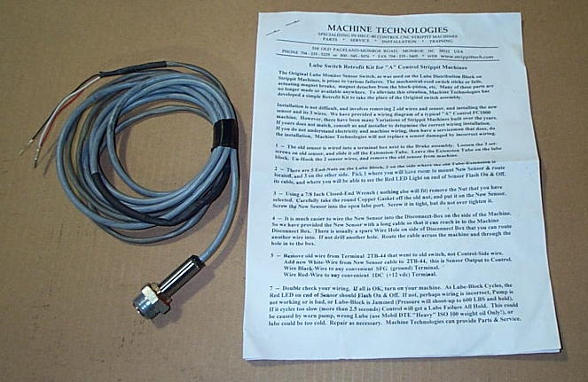
We have Developed our Own Retrofit Sensor Kit to get around these Problems!
Remove Magnet-Tube, and remove Broken Internal Parts, Reattach Tube to Seal that Port
so it does not leak oil. Then remove 1 one of other Port-Nuts, where ever it is Convenient,
and Screw in Retrofit Sensor. Our Sensor is Not Mechanical in Nature,
it Senses Piston as it Moves In & Out, and does Not use the Magnet.
It also has a LED-Light that Flashes On & Off so it is Easy to tell that its Working Properly.
Our Lube Sensor
Retrofit Kit
We have a Kit
for the
CNC HECC80 Control
Machines
and a
Kit for the Old
NC "A" Controls.
11 -- Strippit Used 1/4" O.D. Aluminum Tubing to Route the Lube Oil to Bearings as it is Very Easy to Bend.
However, over time, with
Shock & Vibration of Punching,
they tend to Crack and Break,
Especially just inside
Lube-Fittings where Tube is Tightened
over Farrell-Collar inside the Fitting.
This Allows Oil to Leak-Out and
Not get to the Bearing and eventually Wearing-Out Bearing.
Once a Year, remove Front Inspection Cover and Inspect Lube Lines going to the Crankshaft Bearing.
I replace Bad Lines with New
Soft Copper Tubing and New Fitting.
X, Y, T Axis Problems
"Miss-Positioning" "Jumping Position"
"Running Away" "Over-Shooting"
Axis Positioning is a Quite Complex Subject, as Many Components are involved to make a Complete System. Components (CNC Control, Power Supplies, Servo Drive, Servo Motor, Tachometer, Resolver Feedback Package, Wiring & Cables, Etc.) All have to Function Correctly, or you get the Same Result --- Bad or No Positioning at all.
People & Shops Ignore the Big Picture, Do No Maintenance, and Allow Machine & CNC Control Components to Deteriorate over Time. Then when they have a Problem they look for 1 little thing to Fix, Ignoring Everything Else, to get back Running Quick.
They start Randomly Buying & Swapping (With-Out Professional Help) Circuit Boards, Servo Boards, Motor Brushes, Servo Motors, Feedback Packages, Etc, and make Original Problem Much Worse. Then they Get-Mad & Frustrated at Machine & Everyone Else, Cry they Spent Thousands of Dollars, and have been "Down" for Days, and its still "Not Running". This of Course, is all Before they Finally Request Service.
The Wise Head-of-Maintenance at a Large Manufacturing Plant told me he gave his Maintenance Personal 4 Hours to Fix a Broken CNC Machine. He said, If they could not "Fix-It" in 4 Hours, they would Never fix-it, and then called-in Outside Service People.
If you don't know what you are doing, save yourself Time & Money, and Call a Competent Serviceman in the Beginning, Not after a Week of Part Swapping.
However, in General, Following are the Leading Causes of Positioning Problems;
1 -- Bad #17546-000 Resolver Feedback Package on the End of the Servo Motor.
These Wear-Out, become Intermittent and cause "Jumping". Finally they Fail
Completely and causing Broken Couplings, and a "Run Away" Axis.
2 -- Broken or Loose (4-40 Set-Screws Missing) #17648-000 Resolver Coupling
between the Feedback Package and the End of Servo Motor.
The Most Common Cause of
Axis
"Jumping"
&
"Miss-Positioning"
is a Bad
#17546-000 Resolver
Feedback Package
and
#17546-000
Resolver Coupling
We keep these Parts
In-Stock, and at Half
Strippit's Price!
3 -- Cable Wiring, carrying the Resolver & Tachometer Signals from the Feedback Package to the HECC80 Control, can become Intermittent or even Break Completely.
Strippit used Flex-Conduit to carry the 4-Pairs of Feedback Wires. These Wires are Loose & Unsecured inside the Conduit, so that they Move, Bounce, and Flex Every
Time your Machine Punches and Moves an Axis, and eventually the Wires Break.
This is Especially Prevalent on the Y-Axis of FC1000/3 Machines. Shock of Punching
Travels-Out to the End of the Frame where Y-Servo Motor is Located.
Put your Hand on the Feedback Package at End of the Y-Motor when Punching,
you will be Amazed at Shock & Vibration here!
Strippit Stupidly also used the same Flex-Conduit to Run Feedback-Wires through
Cat-Track to X-Motor on FC1250/30/1500 Machines. Flex-Conduit was Designed to be Flexed One-Time to run A.C. Power to Some Machine, Not to be Flexed Millions of Times Inside the Cat-Track by Y-Axis Movement.
Eventually, the Flex-Conduit Splits & Un-Spirals, Exposing Very Sharp Edges of the Spiral-Metal that Conduit is made of. This then Cuts the Wires inside,
causing Various "Jumping", "Control Shut-Down", and False Error Messages.
To Solve this Problem, we make a New Style Resolver & Tach Feedback Cable.
Our Cable has 3 Advantages;
A -- Our's is a Solid Thick-Armored Cable that does Not use old Flex-Conduit at all.
B -- The Wires in our Cable are Thicker & Tougher than Original Type Cable.
C -- We use Split Clam-Shell Connectors that can be Easily Disassembled in the Field,
to Examine & Repair Wires if Necessary. Because of the Way Strippit Built it,
their Flex-Conduit Cable Can Not be Disassembled to Examine & Repair Wires.
Note, we do not even try to Run New Cable through Machine like Old Cable.
We simply let Cable Hang-Down to Floor, Route it under Machine, and back to the Disconnect Box or Control, depending on the Machine Model.
Also, No Machine is Wired Exactly to the Wiring Prints!
When replacing Any Feedback Cable, you need to take an Ohmmeter and a Long
Clip-Lead Wire, and Ohm-Out the 8 Pins (A, B, D, E, F, G, I, J) on old Cable Connector.
Make a simple Map of Terminals in Disconnect Box where each Wire goes. Then Wire New Cable to the Same 8 Terminals. Wire Mistakes will cause Axis Run-Aways!
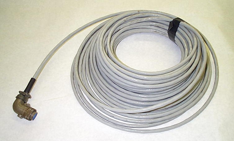
Our Solid-Wire (No Conduit) Resolver Feedback Cables can be Custom-Made
in Any Length,and all use Split Clam-Shell Connector
that Opens-Up for Easy Access for Wire Inspection & Repair.
4 -- Nearby Welding, Especially Hi-Frequency TIG Welding, will cause many control problems, like jumping position, program & memory problems, control resetting, Etc.
Keep All Welders Far Away from All CNC Machines!
5 -- Make sure you have a Good 8-Foot Ground Rod Installed at Back of Machine,
and that the Ground Strap-Wire Connections are Tight!
6 -- Check Servo Motor. If Brushes are Worn to Half Original length, replace them all.
Badly Burnt Commutator & Brushes will cause Rough & Erratic Servo Movement.
If Brushes are so Completely Worn-Out that Metal Brush-Springs are Burning into the Copper Commutator, and Commutator has Rough, Burnt, & Deep Worn Spots,
it is time to Buy a New Motor! Take better care of the New Servo Motor.
7 -- If you get a Red-LED Light On in the Servo Drive, it means Over-Current!!!
Caused by --- Burnt-Out Servo Motor
--- Shorted Wires between the Servo Drive and Servo Motor
--- Shorted Servo Drive Circuit Boards
8 -- People like to Blame CNC Control, Because We Blame what we Don't Understand,
but 4 out of 5 Problems are Actually caused by Something Mechanical
(NOT Electronic) that is Broke, Worn, Loose, or Out of Adjustment on the Machine.
But some Problems are indeed caused by the CNC Control.
Note!!! Strippit made Many Slightly Different Types of the Same Basic Boards! I Often find Problems caused by the Wrong Type Circuit Boards in a Customers Control. Customers with Multiple Machines, or have a Used Machine that came from a Shop
that had Multiple Machines, are Infamous for Having Incorrect Boards in their Controls.
If You don't know what Type Control you have, go to My "Strippit Control Web-Page"
When Replacing Circuit Boards, Make Sure Board Assembly Number is the Same!
Different Dash ( -000, -100, -200, Etc. ) Number Boards are NOT Interchangeable!
Axis Control Boards, usually do Not go Bad, but are Easy to Test;
On HECC80/1 Type Controls, you can Swap the #400470-000 Axis Control Boards between X Slot# 12, Y Slot# 13, T Slot# 14, and see if Problem goes to Different Axis.
On HECC80/30x Controls, you can Swap #400470-100 Axis Control Boards between
the X Slot# 16, Y Slot# 17, and T Slot# 18.
9 -- Swap Position Comparator Boards.
For HECC80/1 Controls, X Slot# 15, Y Slot# 16, T Slot# 17. Note!
Early HECC80/1 used #400474-000 boards, 2MHZ Square-Wave Type, has C1 Cap.
Later HECC80/1 used #400474-200 boards, 3MHZ Square-Wave Type, no C1 Cap.
Late HECC80/1 used #400474-300 boards, 3MHZ Sine-Wave Type, 75k R4, no C1 Cap.
HECC80/30x Controls used #400474-100 boards in X Slot# 19, Y Slot# 20, T Slot# 21.
10 -- Resolver Excitation Board could be Bad. A Good Technician with a Oscilloscope can usually Test it on your Machine. Or Send-In your Circuit Boards to Us and we can Quickly Test, Up-Date, & Repair them, with Final Test in one of our Strippit Machines.
HECC80/1 Resolver Excitation Board is in Slot# 19. 3 Different types were used;
#400468-000 2MHZ Square-Wave
#400468-300 3MHZ Square-Wave
#400272-100 3MHZ Sine-Wave
HECC80/30x used #400272-000 3MHZ Sine-Wave Board in Slot# 23.
11 -- Phase Analog Board could be Bad, but are Hard to Test. HECC80/1 Slot# 18.
#400482-000 Early FC1250/30/1500 with 2MHZ Boards
#400482-100 Early FC1000/2 & FC750 with 2MHZ Boards
#400482-200 Early FC1250/45 with 2MHZ Boards
#400482-300 FC1000/2 with 3MHZ Boards
#400482-301 FC1250/30/1500 & FC1250/45 with 3MHZ Boards
#400482-600 FC750/2 with 3MHZ Boards, and Nibble-Drift Retrofits on FC750
HECC80/30x Controls used #400482-400 Board in Slot# 22.
12 -- "Overshooting" is when a Axis Speeds Past it's New Position by an Inch or So,
then Jerks-Back Violently to the Proper Position. Several Possible Causes;
A -- Weak or Bad Servo Motor
B -- Improperly Tuned Servo Drive
C -- Wrong Compensation Caps & Resisters on PWMC Servo Control Boards
D -- Wrong Type Board in Servo Drive, like PWMP2 where PWMP3 should be in Y-Axis
E -- Wrong Type Boards in Control
F -- Improperly Tuned Control Boards
G -- Bad Connections & Bad Current-Sense Resistor will Limit Current & Motor Torque
H -- Low Servo Power Supply Voltage
12 -- If Switch is Cycling, and sending Proper Switching Signal to Control every 2.5 Seconds
or Less, then you may have a Control Problem.
In the HECC80/1 Series the Machine Switch Isolator Board may be Bad.
In the HECC80/30x Controls, one of the Switch Isolator Boards or G.P.I/O Circuit Boards could
be Bad. Boards can be Sent-In to us for Testing and Repair.
13 -- If you have a Good Lube Pump Pumping Correct Lube Oil, but there is No Pressure indicated on 2 Good Gages, your Machine's Bearing are Loose & Worn-Out. Or you are using the Wrong Too-Light Oil, Probably for Years. Bearings are Not Cost Effective to Replace on a Older Machine. Buy a New Machine and take Better Care of Your Next Machine!
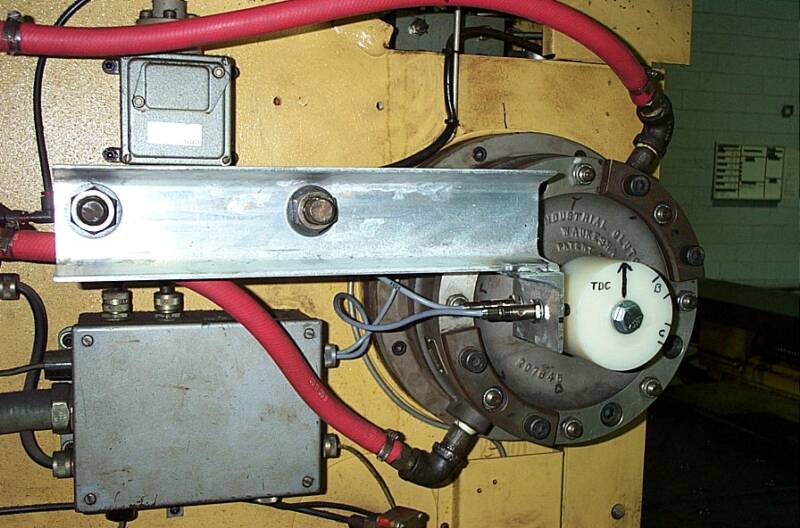
And 2 Photos
of Our
Nylon-Hub and
Prox-Sensor
Retrofit
on a
Strippit
FC1250/30/1500 Machine.
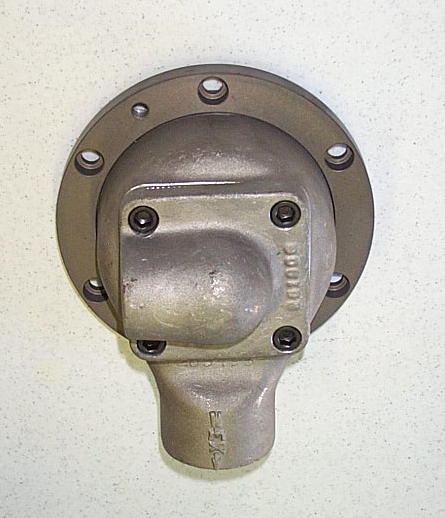
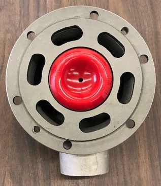
This is the #17363-400
Air-Clutch QRV-Rotary Valve
The #17363-300 Poppit Valve goes
in to Backside of QRV Rotary-Valve.
Note! To Remove Valve to Change Poppit, Remove the
6 -- 5/16" Socket-Head Cap Screws,
then Screw 2 of them into 2 Tapped Holes which will Push Valve off Clutch.
Be Very Very Careful Removing and
Reinstalling Valve as Excess Force will
cause "Neck" Inside Valve to Break,
and Valve will Split into 2 Pieces!
We Keep QRV-Valves In-Stock!


Zeroing X & Y AXIS
Note, Whenever you Change a
Feedback Package, Coupling, Servo Motor, Etc, you will Need to "Rezero" X or Y Axis.
I have a Procedure to Rezero-Axis on the
"Strippit Workclamp" Web Page. Go There!


This page was last updated: January 23, 2026


For Over 50-Years, All Strippit Turret Punch-Press Machines
with Pneumatic (Air) Clutch & Brakes have used the
"Dull Orange-Red" #17363-300 Clutch Poppit Valve, as Shown Above.
These Poppits are made from Cast-Urethane Material and
Will Always Break & Crumble, Sooner or Later, REQUIRING Replacement!
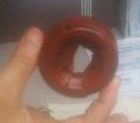
We now use a New-Type "Bright Red" Poppit Valve with 1 Center-Hole
as Shown Below. Part-Number for this New Poppit Valve Kit is #17363-300
and Includes New Poppit, Poppit O-Ring, Small O-Ring for Rotary-Union,
Synthetic "Red" Grease to Coat QRV-Valve-Bore & Outside of O-Rings,
and Installation Instructions with QRV-Rotary Valve Blue-Prints