Sensor Retrofits
In 1970's & 1980's, the Strippit Co. used #18122-000 (1-Meter Long Cable)
and #19684-000 (2-Meter Long Cable) Sensors, both using #17441-000 Magnets,
on most of their CNC Punching Machines for
Brake-On, Clutch-Dump, Ram-Up, Upper Tool-Door, and Tool-Ring Sensor Functions.
These Hi-Speed Hall-Effect Sensors are Obsolete,
and are No longer Manufactured or Available anywhere.
As Original Sensors are Short and Compact, with Special Electrical Characteristics,
finding a Replacement Sensor was Difficult.
Machine Technologies has now Sourced, and Tested-Good,
a New Replacement Sensor and Target Combination on our Strippit Machines,
and we now offer this Retrofit Sensor and Target Kit For-Sale.
Both #18122-000 and #19684-000 Sensors will be Replaced with
Machine Technologies Part Number #18122-RET Retrofit Sensor Kit. Kit Includes
New #17441-RET Target Replaces Old #17441-000 Magnet, and is Required for
Proper Operation. Extra Targets can be ordered using this #17441-RET Part Number.
Because New Target is a little Heavier than Old Magnet Target, we have provided a
Special Kelps-Nut and Thread-Lock Fluid to Secure Target Firmly.
Just apply a Small Drop of Thread-Lock Fluid to Target-Stud before doing the
final Tightening on Keps-Nut.
If Target were to get Loose, it could Hit Sensor and Both could be Destroyed!
This Loosening was also a Problem with old Sensor & Magnet Combination.
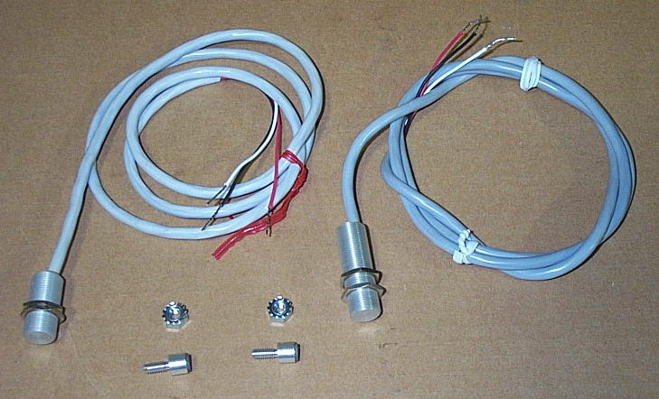
At Left,
Obsolete
#18122-000 Sensor
and
#17441-000 Magnet
with Keps-Nut
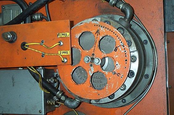
At Right,
Two Obsolete
#18122-000 Sensors
with two
#1774-000 Magnets
on Timing-Disk
being used for
Brake-On &
Clutch-Dump
Press-Drive Timing
on this
FC1250/30/1500
Strippit Machine
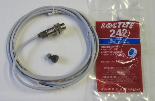
#18122-RET
Retrofit Sensor Kit.
Kit Includes
New Sensor
New #17441-RET Target Keps-Nut
and
Loctite 242 or 243
Thread-Locker Fluid.
Sensor Installation is Easy, and only involves 3 Wires,
But the 3 Wire Color-Codes are Different on Old and New Sensors!
Installer Must Carefully Write-Down What
Terminal-Numbers 3 Old--Sensor Wires were Connected to.
Refer to your Machine's Wiring Prints.
Typically, OLD Sensor Wiring;
RED--Wire goes to 1DC (12 Volts D.C. Voltage)
WHITE--Wire goes to Signal-Out to Control
BLACK--Wire goes to LVR (Ground)
NEW Sensor Wiring;
BROWN--Wire goes to 1DC (12 Volts D.C. Voltage)
BLACK--Wire goes to Signal-Out to Control
BLUE--Wire goes to LVR (Ground)
Double-Check Your Wiring BEFORE You Turn-On Control Power!
All Sensors are Tested-Good Before Shipping.
Sensor Wiring Errors may Burn-Out New Sensor and will be at Customers own Risk.
Set Gap between NEW Retrofit Sensor and Target to .040" (1.0MM),
use a Feeler-Gage to Set Gap Correctly,
and make sure Sensor to Target Alignment Left to Right is Correct.
When Sensor is Over Target,
Sensor will be "ON" and small LED-Light will be "ON" at Cable-End of Sensor.
As some readjustment of Sensor and Target Positions & Gaps may be needed,
do not use Thread-Lock Fluid until you are Satisfied with Machine Operation.
Then go back, remove Keps-Nut, put a small drop of Thread-Lock Fluid on Target-Stud Threads,
and Firmly Tighten Keps-Nut.
This page was last updated: June 12, 2025
Ram-Up Application
When using Sensor in Ram-Up Application, make Sure that Punch-Ram is All the way Up
into the T.D.C. Top-Dead-Center Position Before you set Sensor and Target Gap.
If Not Properly set at T.D.C. Position, Target will Crash into Sensor, Destroying Both.
There is usually a "Mark" or "Notch" on Timing-Disk to Indicate T.D.C.
This Mark will be at the very Top 12 O'clock Position when Press-Drive is at T.D.C.
If Punch-Ram is Not at T.D.C.,
Push-Down and Twist-to-Lock Activation Button on Brake MAC Valve to Release Brake
which is holding Press-Drive in position. Now you can grab Timing-Disk by hand, and
Rotate Timing-Disk Back--and--Forth until Mark is in T.D.C. Position.
Release Mac Valve to Hold position.
Now set NEW Retrofit Sensor & Target Gap to .040" (1.0mm).
If still using OLD Sensors & Magnets, set Gap to .025" (0.63mm)
Setting Clearance Gap on
Clutch & Brake Timing Sensors & Targets / Magnets
1 -- Rotate Turret, by Hand if necessary, so there is No-Tool under the Ram.
2 -- With Machine Power Turned-Off, take a small screwdriver, Push-In and Twist
Actuator-Button on Brake Mac Air-Valve to Lock-On & Activate Air-Valve,
which will Release the Brake. This will allow Crankshaft to be Rotated.
3 -- Grab Aluminum Timing-Disk with Both Hands, and Push & Pull Hard on it.
If you feel a "Clunking" as you Push & Pull,
This is Slop & Wear in End-Bearings allowing Crankshaft to Move Back & Forth.
End-Bearing Wear can cause Improperly-Set Sensors and Magnet / Targets
to "Crash" and be Destroyed.
End-Bearing Wear is Caused by Shop Knuckleheads putting Wrong Oil in Press-Drive
Lube-Tank when Machine Stops with a "Lube Failure" Fault caused by Empty oil tank.
Knucklehead's then Grab the First Oil-Like Substance they can find,
Usually Hydraulic Fluid, and then dump that into Tank, instead of Proper Lubricating Oil.
Read about Lube System & Correct Lubrication Oils on
4 -- Grab the Timing-Disk, and Rotate Disk (and the Crankshaft) until
Clutch-Off ( Inner-Track Target / Magnet) Target / Magnet is over it's Sensor.
Make sure Sensor & Target / Magnet are Aligned Closely Left to Right,
and are NOT Off-Set to each other. Fix if necessary!
5 -- Push Disk Hard to Take-Up the Slop between NEW Retrofit Sensor & Target ,
then Set Gap Between Them to .040 inch (1.0mm).
If still using OLD Sensors & Magnets, Set Gap to .025" (0.63mm).
This way, Crankshaft can Only Drift Magnets & Targets AWAY from Sensors
and NOT into them, to Avoid Breakage of Sensors & Targets & Magnets!
6 -- Repeat with Brake-On (Outer-Track Target / Magnets) Sensor & Target / Magnets.
7 -- Rotate Ram Back-up to Top-Dead-Center (T.D.C.) and release Brake Mac Air-Valve.
8 -- Turn-On Machine, and "Punch" a couple of times.
Ram Needs to Stop Consistently at Top-Dead-Center (Notch at 12 O'clock) Position,
or Better-Still, a Bit Before at the 11 O'clock Position!
If Ram Stops-Too Early, Retard the Brake-On Target / Magnet a Couple of Hole Positions.
If Ram Stops Too-Late, Advance the Brake-On Target / Magnet a Couple of Hole Positions.
If you cannot get Ram to Stop at T.D.C., there may be Other Issues such as
Worn Brake & Clutch Assemblies, Sticking Clutch & Brake Mac Valves, Broken Clutch Poppit Valve, Clogged Air Filters, bad Air-Regulators, Etc., that Will NEED to be Repaired!

Off to See