Strippit 20-Station Turret-Drive
Problems & Fixes
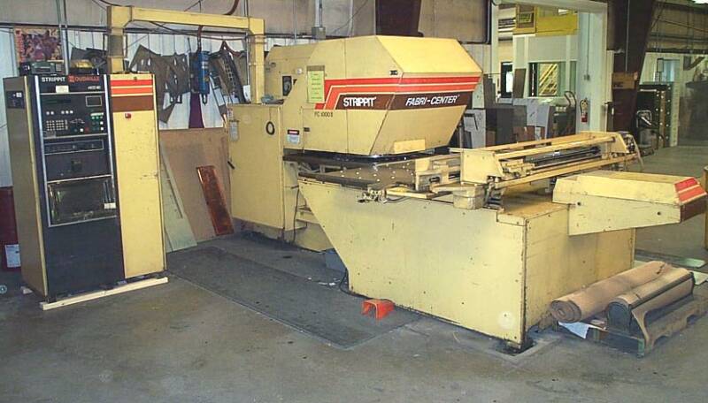
In 1975, Strippit Introduced their FC1000 Series of Machines. These Machines had a
20-Station Bi-Directional Servo Controlled Turret, so the NC & CNC Control could
always Plot & Move Shortest-Path to the Next Tool Station that was Programmed.
This was a Large Improvement over Crude Clutch & Brake 1-Direction 20-Station Turrets that Strippit used on FC30/30 & FC30/40 Machines built in the early 1970's.
This discussion does not pertain to these early FC30/30 & FC30/40 Machines.
If you Still have a FC30/30 or FC30/40 Machine, You Should Scrap-it Today!
Strippit
HECC80/1
CNC Control
FC1000/2 Machine
First 2 years production of FC1000's used Turret-Drive System with a Odd Gearbox with
Servo Motor Underneath Gearbox Hanging Upside-Down so Resolver Feedback Package
almost touched shop floor. This system actually worked quite well, but had 2 Problems.
It was almost Impossible to adjust Resolver and Oil Leaking out of Gearbox ran directly
into Servo Motor & Resolver causing many Problems.
Most of these old A-Control NC FC1000's have been Scrapped and Most of this
discussion of Fixes does not apply to this type of Turret Drive.
About 1976, Strippit Redesigned Turret Drive into the 2nd and Most Common Type.
This 2nd Type of Turret-Drive was thereafter used in all FC1000/1, F1000/2, and FC1250/30/1500 Machines until the 33-Station Machines came out in early 1980's.
Over 500 Machines were built with this type of Turret-Drive. Many are Still in active production use, and we will show some of their Problems and Fixes.
Bi-Directional Turret-Drive is Great for Production Productivity (Saves Time) but is Hard on the Drive Components. Mechanical Engineers call it a
"Reversing Load" and it is hardest type of Work-Load on Drive Components.
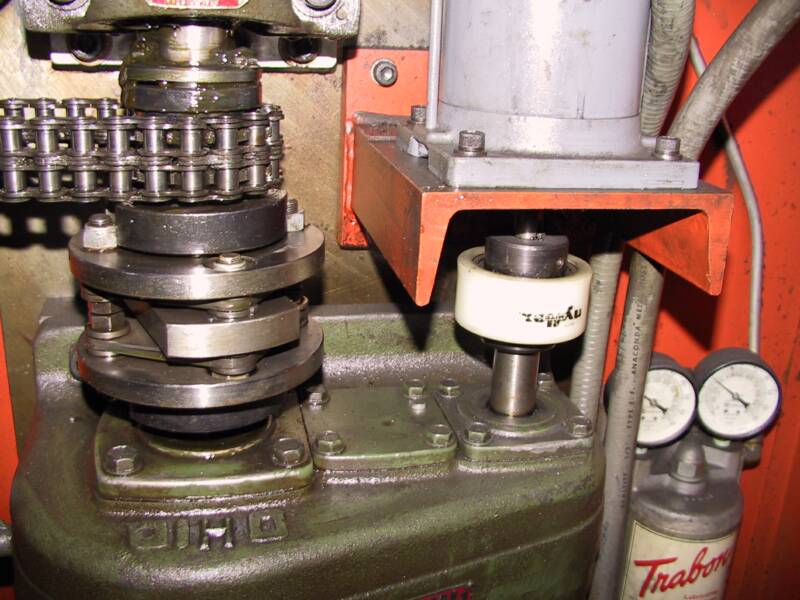
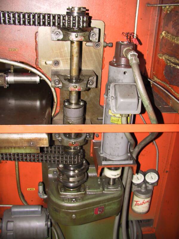
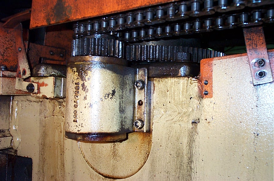
This 2nd Type had a New Gearbox Type, with Servo Motor now mounted above Gearbox, and Resolver Feedback Package pointed Upward were it was fairly easy to get at.
ThisTurret Drive actually worked
Quite Well when new, but over time,
System Loosened-Up and became Mechanically Sloppy from the Thousands & Thousands of Back & Forth Turret Moves, as well as "Crashes" from Operators putting in "Too Tall" Tools that would Crash into the Ram when Turret was Rotated.
So Turret Rotation-Positioning would Gradually Deteriorate, Shotpins would "Clunk-In" Harder & Harder, until Finally, they would Not Go-In at All, and Machine would Stop with a "Pins Timeout" and a
"All Hold Condition".
At this Point, You Need to
Rebuild the Turret Drive System!
There are 2 ways to Rebuild the Drive System.
You can Rebuild it as it was Originally, or you can try to Improve it.
To Rebuild it as Original;
1 -- Loosen the Drive Backplate & Jack-Screws, and remove 2 Drive Chains.
2 -- Pull the Upper and Lower Turret Sub-Assemblies.
This is hard to do with out a Dowel Pin Puller. See Dowel Pins & Dowel Pin Puller!
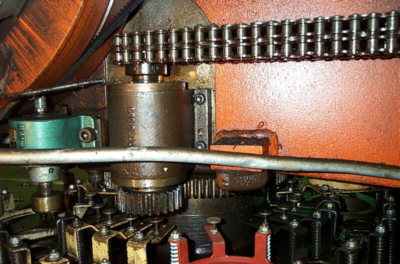
3 -- Un-Spiral the Upper & Lower Rings on the Big White Output Gearbox Coupling,
so that it is "Free" from the Drive Shafts.
4 -- Unbolt the 3 Pillow-Blocks so that Drive Shaft can be Removed,
Pull it out, and set it on a work table.
5 -- Replace All the Keys in 2 Sub-Assemblies, Chain-Sprockets, and Top & Bottom
of Coupling. All Keys Must be Very Tight!!! If Keys are Not Tight, they will start
"Rocking" as soon as Turret is used again (Reversing Load, Remember?), and
will start wearing out again Immediately. I have a local Machine Shop
Surface-Grind me Special .002" Oversize Keystocks ( .252" and .377" sizes),
Bevel the Ends and the 4 sharp side-corners, then Press-In Tight Keys with a
Arbor-Press, or Very Carefully Pound them in with Brass Rod & Brass
Hammer. If they are Not Very Tight, Do it over again until they are!
6 -- Many times Top & Bottom Turrets will "Slip" out of Position with each other too
easily. This is usually because Friction Coupling between Upper and Lower Drive
Shafts is Not Centered Properly, and it Holds 1 Shaft better than the other.
Take apart Coupling, clean it, and install it on the Lower Shaft.
Make sure End of Each Shaft is in the Middle of the Coupling and almost touching.
7 -- Install Top Shaft and Top of Coupling, but do Not Tighten fully.
8 -- Reinstall Sub-Assemblies, Drive-Shaft, Coupling, and Chains on Machine.
9 -- Using the 2 Jack-Screws, Jack the Backplate Backwards so the Chains are pulled
tight, but Not Too tight. Tighten Backplate Bolts to Machine Frame..
10 -- Using a Steel Bar in a Shotpin Bushing, Carefully turn Lower Turret, then Upper
Turret, and Position Same Tool Station Under the Ram. Manually Fire-In the
Shotpins, Turrets should both Pull-In to Position as the 2 Shotpins go in. Manually
Fire Shotpins In & Out several times, Turrets should NOT "Scissor" or Move as
you do this. If they do, Manually, with a Bar, move them slightly, and repeat
with Shotpins until they Do Not Move.
11 -- Now Tighten Top of Shaft Coupling. I use Hardened Washers under the Screws.
12 -- The last thing to do, is to "Rezero" Turret. I have a Precise Way of doing this
with an Oscilloscope, but you don't have that option. Turn-On Machine, and Try
to "Home" the Turret. If Shotpins go in, Great. If not, Turn Resolver in the
Feedback Package on End of the Servo Motor a 1/4 turn, Hit the "Clear-All"
Button on Control, and try again until they finally Clunk-In.
13 -- Have someone Index the Turret Station-To-Station Back & Forth (Station 1 to 2 and
back to 1 repeatedly) while you Slowly Turn Resolver Back & Forth until you get
Best Turret Positioning, in Both Directions, as the Shotpins Fire-In.
Try to Not get Your Fingers & Arm Caught in the Chains!!!! There will Still be some
"Slop" in the System, as there is Slop in Gearbox, and output Coupling is Very
Loose by Design. We are trying to Balance the remaining Slop by Positioning
Resolver-Setting in the Middle of it, as Turret goes Back & Forth. Lock-Down the
2 Resolver Screws, do Not Over-Tighten Screws as they Strip-Out Very Easily!
The
Upper Turret
Sub-Assembly
The
Lower Turret
Sub-Assembly
At Machine Technologies,
We Always Try to Improve the Original Design where Possible.
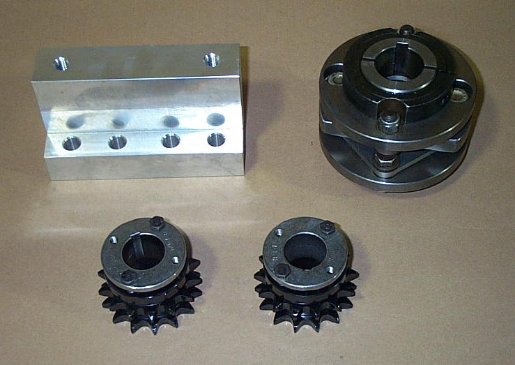
1 -- We rebuild the Turret Drive, much like the above Instructions. But we use some Newer & Better Parts to try to Improve the Drives Performance & Longevity.
First, we use 2 Taper-Locking Chain Sprockets that "Grip" Drive Shafts,
and do not depend on Just the Little 1/4" Keys to Handle Rotational Torque. Keys are the Weak-Link in this Drive System.
2 -- Then we use a Custom-Made Gearbox Output Coupling to Replace the Sloppy Original Coupling.
This does 2 Good Things for us;
--- It Eliminates All the Internal Slop that the Original Coupling Has Built-In.
--- It Tightens & Locks onto the 2 Shafts in Addition to still using the Keys, so it handles the Torque Much Better without wearing & loosening.
Because there is so little space to work with, we also make a Off-Set Block to Move the Lower Pillow-Block Upward so that we have enough space to fit the New Coupling.
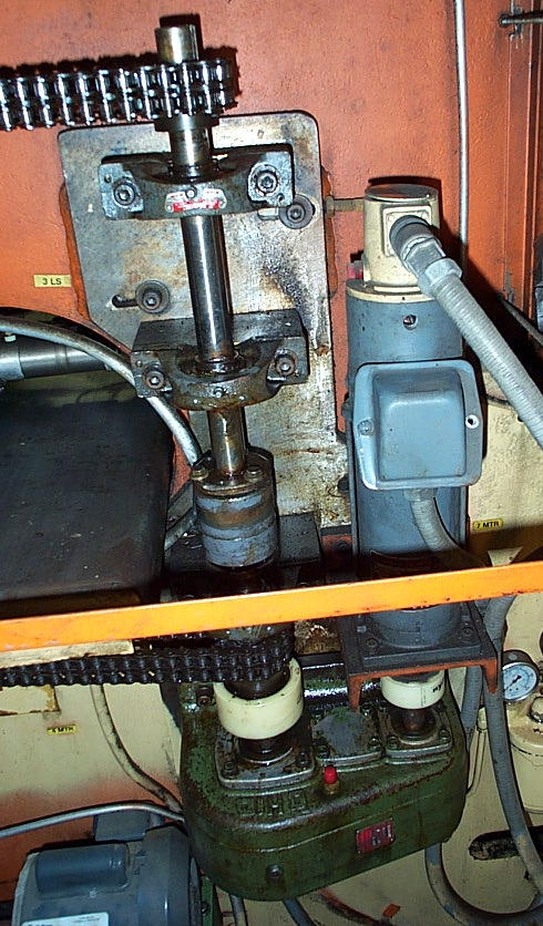
3 -- When Done, the
Rebuilt Turret Drive System, with New Parts, will looks like this.
The New Parts are Not Cheap, but it does make System Work Much Better when Properly Installed.
Either Way, Rebuilding the Turret Drive System will Probably take you 2 Days,
and is a Dirty Job.
Take your Time,
and Do It Right!
Because it is Necessary to Rebuild it Right if you want your Machine to Work Well, and make the Parts you need.
This page was last updated: February 9, 2026

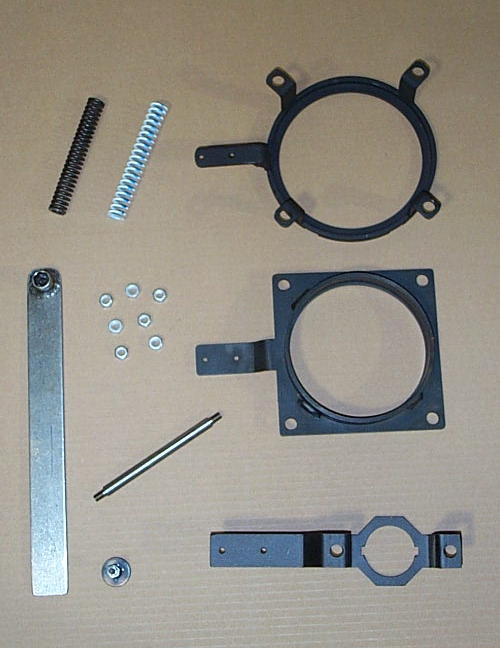
--- Standard Strippit Lifter Spring,
Part #17591-000
--- Our Heavy-Duty Lifter Spring for 3 1/2" Stations Only, Improves Stripping Action, Part #17591-HD
--- 3 1/2" Tool Lifter,
Part #100245-000
--- Stud Nut, Part #17590-000. Replace Every Time you Remove a Stud, as a Stripped-Nut is almost Impossible to Remove from Under Top Turret. Our's does Not Strip Threads as easily as Original Nuts Strippit used!
--- 2x2 Notch Unit Tool Lifter in Station #1 in Most Older Strippit Machines, Part #200285-000
--- Lifter Stud, Part #100726-000
--- Strip-Target, for all 3 Lifter Types, Part #17351-000
--- 1 1/4" Tool Lifter,
Part #100811-000
--- Make Yourself a Stud-Nut Removal Tool (Like in Picture Above) by Welding
a Short (Grind It Down) 6-Point 7/16" Socket on 1" x 10" Piece of 1/8" Steel.
You can also use it as a Feeler Gage to Maintain the 1/8" Gap under Strip-Sensor.
And Now Is The Time To Fix All The Tool Stations In Upper Turret!!!
We Keep All The Repair Parts Shown Below, and Many Other Parts, In-Stock!
Note! Over Time, Many Gearboxes slowly Lose All the Gear Oil Inside,
Drip by Drip, Until the Gearbox is Empty. Then, Your Gearbox Slowly Grinds the Gears and Bearing to Metal Dust. Check Oil Level Yearly!
Gearboxes are Hard to Fill. I have Found that the Best Way to Fill,
is to Remove the 4 Bolts & the Middle Cover Plate,
then to Very Slowly Fill Gearbox to the Top with 90 Weight Gear Oil.