Strippit and General Electric
Model 2 & Model 3 Hi-Ak Servo Drive
PWMC Comp-Values
In 1970's and 1980's, before Neutron Jack Destroyed The U.S. CNC Control Industry,
General Electric Co. was the World Leader in CNC Controls and Servo Drives.
These CNC Control & Servo Systems were Widely Used on Hundreds of Different Models of
Lathes, Mills, Machining Centers, and of Course, Strippit Turret Punch Machines.
G.E. Hi-Ack Model 2 and 3 Servo Drives Provided the Power for Machine Axis Motion Control.
CNC Machines have Great Variations in Axis Speeds, Weight, and Rigidity. To Provide Machine Designers
a way to Compensate for these Variations, G.E. Provided on All PWMC Servo Control Boards Terminals
where Machine Designers Selected and Installed
Unique Values of Several Resistors, Capacitors, and Zener Diodes
as a way to Taylor Servo Response of Each Individual Axis for each Type and Model Machine.
This Important Comp Value Information should be Provided in Original Machine Manufactures
Schematics and Service Manuals, and Copies of these Important and Unique Comps for Each Axis
should be Carefully Copied and Preserved!
Unfortunately, Like Egyptian Hieroglyphics, the Knowledge that All PWMC Boards
Have to be Properly Configured with Correct Compensation Values, and More Importantly
What these Values Should be for Each Individual Axis on Each Machine, is Rapidly Becoming Lost!
If Wrong Comp Values are Installed on PWMC Board, or "Double" Comp Values Installed,
the Machine Axis will Position Poorly, Over-Shoot, Oscillate, or Not Position and Run at all!
Damage to Power-Boards, Power-Modules, Servo-Motors, and Machine could also result.
When G.E. Built these Boards,
G.E. Installed a Standard TEST-Set of Comp Valves Just for their Testing Procedures.
TEST Comp Component Values will NOT be Correct for Axis on Most Machines,
and usually will Need to Be Changed Per The Original Machine Manufacturers Specifications!
As I Sell and Repair PWMC Servo Boards, I am Finding Same Problems Over and Over Again
caused by Uninformed Technicians and Servicemen making Mistakes at their Shops and Factories.
1 -- Swapping PWMC Boards (Without Changing the Comp Values!) Between Different Machine Axis,
or even Worse, Between Different Machines, Causing Multiple Problems on Multiple Axis and
Losing what the Correct Comp Values Are for All Axis on their Machines!
2 -- Installing a New or Repaired Board from a Test Facility that has Test-Comp Values Installed,
but NOT the Correct Comps for this Particular Machine and Axis.
3 -- Installing Incorrect Comp Values for a Particular Machine and Particular Axis, by Perhaps, Copying
Wrong Comp Values from Old Board and Installing the Same Wrong Comp Values on New Board.
4 -- Installing New Comp Values Without Removing All Old Test Comp Values so that you
now have "Double" or 2 Sets of Comp Values Installed!
If you are having Servo Problems with G.E. Hi-Ack Model 2 and Model 3 Servo Drives,
I would Always Check that Comp Values are Correct on Each-Axis for this Particular-Machine!
General Electric
Model 2 PWMC3 and Model 2UL PWMC4
Servo Control Boards
PWMC3 Series was the First Type of Model 2 Servo Control Boards.
First Version was PWMC3, but Boards were Continuously Improved over the Years
into Newer PWMC3B, PWMC3C, PWMC3D, PWMC3E, PWMCF, and Final Version PWMC3G.
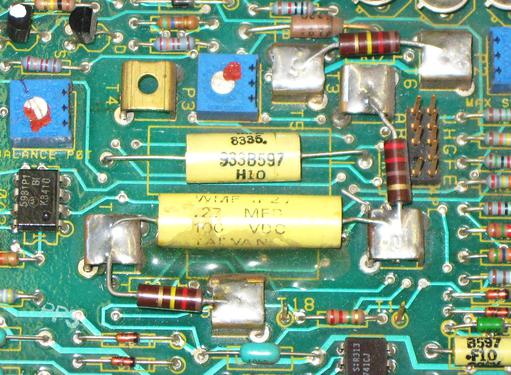
These Boards had 10 Screw-Terminals (Except for PWMC3F which has 10 Solder-Posts) where
G.E. Test Comp Values or Customer's Machine Comp Values are Installed, as Shown in Photos Below.
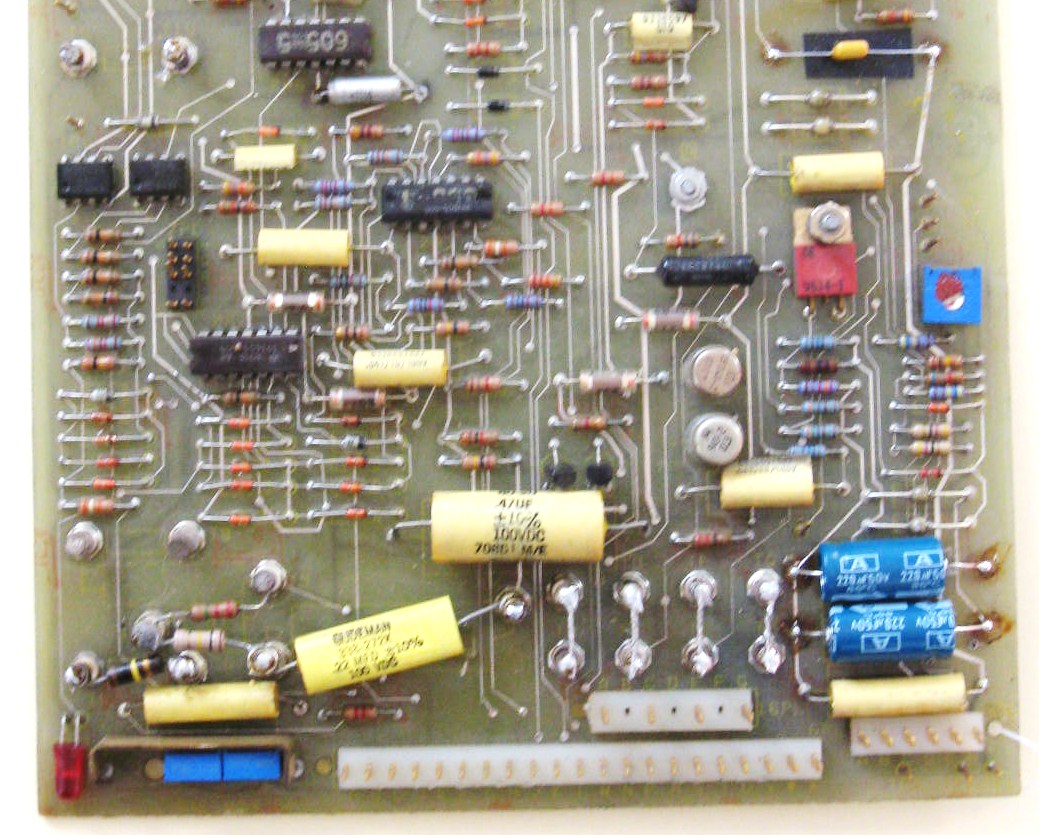
PWMC3 Servo Control Board Type
with
10 Screw-Terminals for Comp Values.
Boards have
2 Connectors 5PL and 6PL.
Versions
PWMC3, PWMC3B, PWMC3C,
PWMC3D, PWMC3E, and PWMC3G.
These Photos are Not showing
Complete Circuit Boards,
but are
Emphasizing the
Comp Parts Installation Area.
PWMC3F had 10 Solder-Posts for Comp Values.
This was the First "U.L."
(Underwriters Laboratories) Type Board
Developed for Increased Safety and Reliability. PWMC3F also has a 3rd Connector 16PL
where Board Received D.C. Power.
U.L. Boards went into a U.L. Servo Chassis.
G.E. Eventually Redesigned All Boards
and Chassis into New U.L. Types.
PWMC3F and New U.L. PWMC4 Boards were Virtually Identical and were simply
Updated Old PWMC3E Boards.
PWMC3F Board could also be Used in Older
Non-U.L. Chassis by Soldering 4 Jumper Wires Across 8 Solder-Posts like Photo at Right.
Board would then get it's D.C. Power from
5PL and 6PL like Older Boards in the Series.
PWMC3 Series Boards Left the G.E. Factory with Standard Test Comp Values Installed.
These Values were; R1 2.2 M Ohm, R2 47K Ohm, R3 10 Ohm, C5 .47MFD Capacitor.
PWMC4 UL Series Boards Left the G.E. Factory with Slightly Different Test Comp Values Installed.
These Values were; R1 2.2 M Ohm, R2 68K Ohm, R3 10 Ohm, C5 .47MFD Capacitor.
At The Strippit Company, These G.E. Test Comps were Removed,
New Comp Valve Parts were Engineered and Added to Board to Provide
Optimum Servo Drive Response for Each Axis on these High-Performance CNC Turret Punch Machines.
Following are a List of Comp Value Components used by Strippit on Machines with Model 2 Drives.
Machine Type X-Axis Y-Axis T-Axis
R2 R3 C5 RL CL R2 R3 C5 RL CL Diode R2 R3 C5 Diode
FC750 & FC750/2 100K 100K .22 -- -- 100K 47K .27 -- -- -- -- -- -- --
FC1000/1 30S/3 100K 47K .22 -- -- 100K 47K .27 -- -- -- 100K 47K .33 1N5231 5.1V
FC1000/1 HC 100K 47K .33 -- -- 100K 47K .27 -- -- -- 100K 47K 1.0 1N5231 5.1V
FC1000/1 "A" Rev. D 100K 47K .33 -- -- 100K 47K .27 -- -- -- 100K 100K 1.0 1N5231 5.1V
FC1000/1 "A" Rev. F 100K 100K .22 -- -- 100K 100K .27 -- -- -- 100K 100K .33 --
FC1000/2 HECC80/1 100K 47K .22 -- -- 100K 47K .27 330 .022 -- 100K 47K .33 --
FC1250 51S/4 Y Size3 100K 47K .27 -- -- 100K 47K .47 -- -- -- 100K 47K 1.0 --
FC1250 "A" Y Size4 100K 47K .27 -- -- 100K 47K .47 -- -- 1N5231 5.1V 100K 47K 1.0 --
FC1250 "A" Y Size5 100K 47K .27 -- -- 100K 47K .47 -- -- 1N753B 6.2V 100K 47K 1.0 --
FC1250 HECC80/1 100K 47K .27 -- -- 100K 47K .47 (330) (.1) 1N753B 6.2V 100K 47K 1.0 --
FC1250/30/1500 H80/1 100K 47K .1 -- -- 100K 47K .33 -- -- 1N753B 6.2V 100K 47K .33 1N5231 5.1V
" H80/1 33-ST. Laser 100K 56K .1 -- -- 100K 56K .33 -- -- No Diode? 100K 75K .33 NO DIODE
" H80/306 33-ST. 100K 47K .1 -- -- 100K 47K .33 -- -- No Diode? 100K 47K .33 NO DIODE
FC1500/45 (D.R.) 68K 100K .33 220 .1 50K 31K .27 (330) (.022) -- 100K 47K .33 (RL330 CL.022)
FC1500/45 2nd 100K 100K .33 220 .1
Notes;
--- Zener-Diodes Provide Current Limiting to Protect Servo Drive and Servo Motor,
Lower Zener Voltage means Lower Current
--- RL and CL Parts Provide High-Frequency Attenuation
so that Axis does Not Oscillate and "Buzz".
--- RL and CL Parts, In Brackets, I add to Problem Machines to Cure High-Frequency Oscillation
so that Axis does Not Oscillate and "Buzz". The Point is that some Comps may Need to be Adjusted
for some Machine's Axis to Run OK.
--- At Strippit Co., we Left the R1 2.2M Ohm Resistor on All PWMC Boards,
Removed Other G.E. Comps Parts, then Added Proper Comp Values for that Machine
and Axis Per Chart Above. Chart Values Shown Just as an Example!
PWMC7 and PWMC8 Boards leave the
G.E. Factory with 7 Screw-Terminals,
with All Screw-Terminals Left Empty.
BUT, The G.E. Test Comp Parts were Soldered Directly to Circuit Board,
so this made it
Very Easy for the Uninformed to Add our Strippit Machine Comps to Screw-Terminals and now you have "Double" Comp Parts
on Board and your Machine would Not Run!
This is A Very Common Problem!!!
At Strippit, we Left-On R10 2.2M Ohm and C8 .1MFD, but Carefully Cut-Off
R9, R11, R17, and C7, then Added Our Replacement R9, R11, R17, and C7
Comp Values to Proper Screw-Terminals.
On Strippit FC1000/3 Machines Servo was Mounted on Punch Machine Frame and was Subject to Much Vibration. So, Instead of Using Screws, we Removed Screw & Nut from Terminals, and Soldered Our Comp Values Directly to Terminals for a Very
Secure Connection, like in Photo at Right.
G.E. Hi-Ak Model 3 and 3A Servo Drives were Designed to be a Higher-Voltage (150 Volt .D.C.)
and Higher Performance Servo Drive than the Older Model 2 (90 Volt D.C.) Servo Drive System.
Early Model 3 Drives used a PWMC5 Board to Drive 2 Power-Modules
and PWMC6 Board to Drive 4 Power-Modules for Higher-Current Capacity.
The Original Model 3 Drive was Not Reliable, so G.E. Engineers Redesigned
All Circuit Boards and Servo Chassis in to Much Improved Model 3A Servo Drive.
PWMC5 Board was Replaced by Improved PWMC7 Board.
PWMC6 Board was Replaced by Improved PWMC8 Board.
If you still have an Old PWMC5 or PWMC6 Board in your Model 3 Drive,
Throw It Away and Replace it with Improved PWMC7 or PWMC8 Board!!!
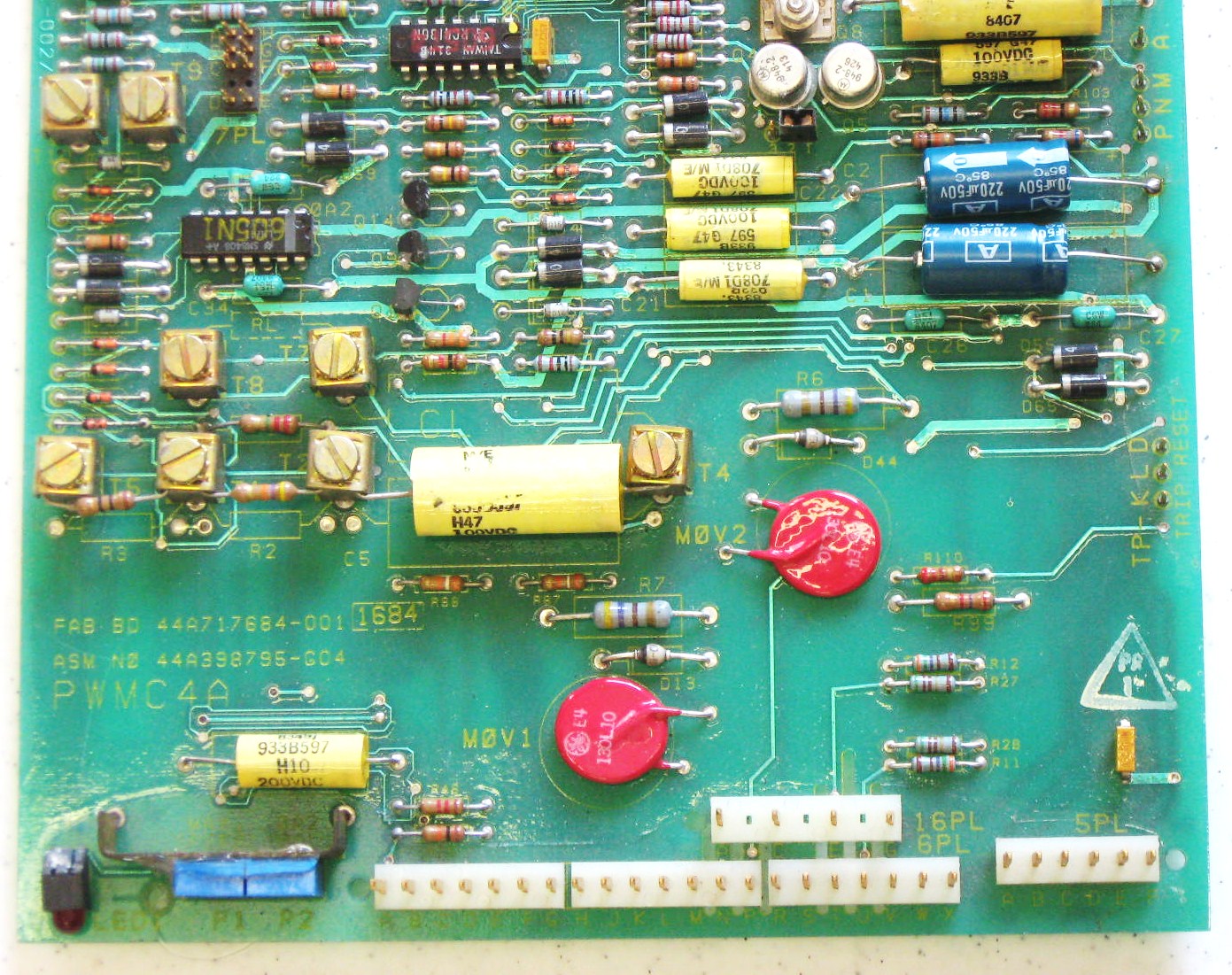
Early U.L. PWMC3F and PWMC4 Boards
were Redesigned into
PWMC4A and PWMC4B Servo Control Boards.
PWMC4A and PWMC4B Boards were
Very Cleverly Redesigned to be
Backwards Compatible with
All U.L. and Non-U.L. Chassis,
And did Not Need or Have the 8 Solder-Posts
that PWMC3F and PWMC4 used.
NOTE that PWMC4A and PWMC4B Boards
used 8 Screw-Terminals for Same
Comp Values that Older PWMC3 Boards
used 10 Screw-Terminals for.
So if Replacing a PWMC3 Board with a
Newer PWMC4A or PWMC4B Board,
do NOT use same Screw-Terminal Numbers
as Screw-Terminal Numbers have Changed!
Instead, Use Comp Value
Part Number Printed on the Board.
Example, on
PWMC3 Boards R3 goes Between T5 and T6,
But on
PWMC4A Boards R3 goes Between T5 and T1.
PWMC7 and PWMC8 Boards
are Very Similar,
Except
PWMC7 Board Drives
2 Power-Modules
and the
PWMC8 Board Drives
4 Power-Modules
for Higher Current Requirements.
General Electric
Model 3 and Model 3A Hi-Ak Servo
PWMC7 and PWMC8 Boards
PWMC7 and PWMC8 Boards Left G.E. Factory with Standard Test Comp Values Installed.
These Values were; R1 2.2M Ohm, R9 47K Ohm, R11 1K Ohm, R17 10 Ohm,
C7 .68MFD Capacitor, C8 .1MFD Capacitor.
For Strippit FC1000/3 and FC1500/45 Machines, we Left-On R1 and C8,
and Cut-Off R9, R11, R17, and C7
then Added New Comp Value Parts Per the Chart Below.
Machine X-AXIS Y-AXIS T-AXIS
R9 R11 R17 C7 R9 R11 R17 C7 R9 R11 R17 C7
FC1000/3 120K 220 120K .27 UF 120K 220 120K .27 UF 120K 220 75K 1.0 UF
FC1500/45 120K 220 120K .27 UF 120K 220 120K .27 UF 120K 220 75K 1.0 UF
Monarch Machining Centers, Gidding & Lewis Horizontal Mills, and Warner & Swasey CNC Lathes are
the only other Manufacturers I have seen, Beside Strippit, that also used Model 3 & 3A Type Servo Drives.
As Most of these Old machine Tool Companies are now out of Business, Try to Find
Original Comp Values for your Machine in Your Schematics and Service manuals!
If your, Non-Strippit, Machine Axis is Not Positioning Well, and Original Comp Values have been "Lost",
Try to get them from Original Machine Manufacturer!
If Not Available, a Smart Technician or Engineer will NEED to
Read Set-Up Information in Correct G.E. Servo Manual and Experiment to Find Values that will
Allow Smooth Acceleration and Deceleration of Axis with No Overshoot or Oscillation.
You can use G.E. Test Comp Values as a Starting Point, and use Strippit Machine Values as Real-World Examples Selected by Real Electronics Engineers.
On Strippit's, X Values were for Light X Axis, and
Y and T Values were Selected for Heavy Y and T Axis.
Adjust Valves Very Carefully until you achieve Performance you need.
I have Worked on some of these Other Brand Machines, and have been Amazed at how Poorly Servo
System was Integrated with Poorly Chosen Comp Values on PWMC Boards, and Improper Handling of
Servo Inhibits and Contactors. It's hard to Explain to Customer that His Machine was Poorly Engineered
and That's why they have Problems, But I get the Retort "Well, it's Run Pretty Much OK for 30 Years".
I have come to Really Appreciate what Good Engineering was done at Strippit, in The Old Days.
Nowadays, with Most Real Engineers having Left Strippit, Not So Much Anymore......
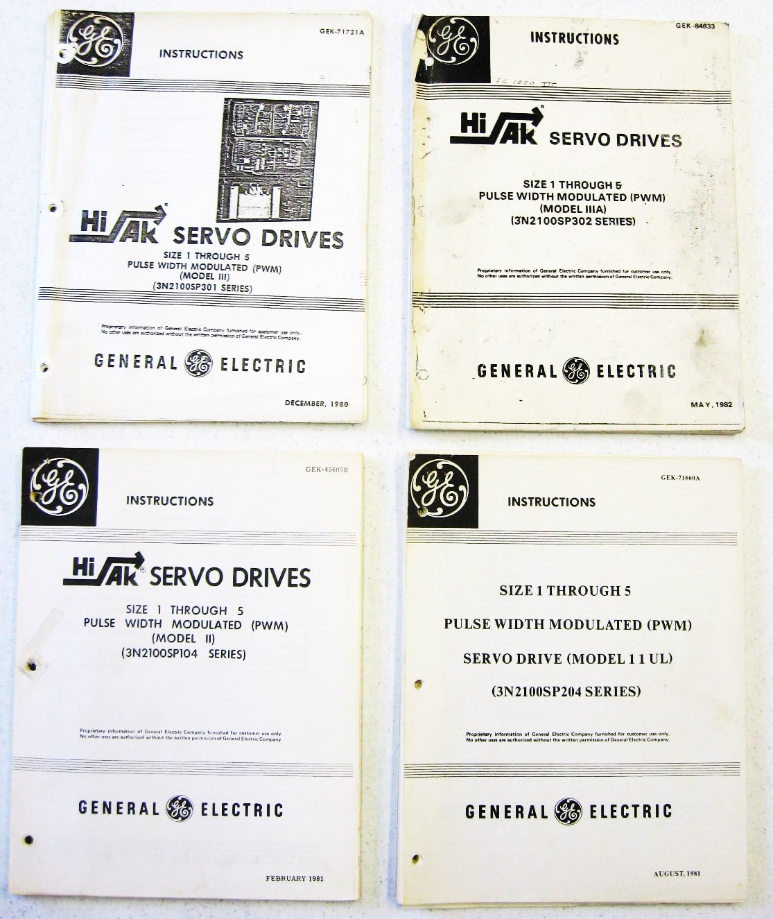
We have Small Stock of
G.E. Hi-Ack
Servo Drive Manuals For-Sale
if you have Lost Yours.
These come in 4 Types;
--- Model 2
--- Model 2 UL
--- Model 3
--- Model 3A
You and Your Serviceman
Cannot Work on
Your Machine's Servo Drives
Without
The Correct Manual!


This page was last updated: June 19, 2025

Please Read
these Related
Servo-Drive Web Pages Also!