Strippit FC1000/3 Machine
Problems & Fixes
All FC1000/3 HECC80 Machines used G.E. Model 3 or Improved Model 3A Servo Drives.
These Servos were not widely used in the Industry, can be hard to repair, and Parts are somewhat Expensive & Hard to get. Its Best to do everything you can do to Avoid Servo Problems!
There are More Pictures and Discussion of these Servos on my 2 Servo Web-Pages. Read Them!
These Machines & Servo Drives are actually fairly reliable, but they are all 30+ years old now,
Should have Regular Maintenance, and I would Even "Baby" them a little to Minimize Problems.
However, Typical Shops Gives Them Zero Maintenance and Is Surprised when they Finally Fail.
Typical Failures are Red LED-Lights On in Servo Cabinet which means Over-Current, and
CRT-Display will show a "Servo Down" Message. This is usually caused by
Burned-Out Servo-Motor, and/or Blown Power-Modules, and/or Blown PWMC7 & PWMC8
Servo Control Boards, and/or Shorted Wiring between Servo-Drive and Servo-Motor.
Blown Power-Modules Can Blow The Servo-Control Boards,
AND
Blown Servo-Control Boards Can Blow The Power-Modules!
You have to Replace All Bad Modules & Boards & Motors at The Same Time,
Or You Risk Blowing Them Again The First Time You Put Power On To Machine!
To Minimize Servo-Drive Problems, Do ALL Of The Following!!!
1 --- Incoming AC Voltage to Machine is the Most Important Factors of Servo Reliability. Because of the 2-Speed Press Drive Motor, FC1000/3 Machines are all Single-Voltage Machines.
That is, they are Wired for 230 Volts AC, OR are Wired for 460 Volts AC, and can Not be changed.
Your Machine's voltage is Stamped on Metal-ID Plate on back-side of the Machine.
High AC-Voltage Causes High DC Servo-Buss Voltage
which is the Major Cause of Servo Drive Failures!!!
I Recommend that Machines Wired for 230 Volts have the
incoming voltage at 220 to 230 Maximum!!!
I Recommend that Machines Wired for 460 Volts have the
incoming voltage at 440 to 460 Maximum!!!
If your Voltage is Higher, Reduce it! Get Power Company to Change Transformer-Taps on your Power Poles Outside. Some Shops also have their Own Inside/Outside Transformers for the whole building, have your Electrician or Power Company Change the Taps in it if Necessary.
And finally, you can add Boost-Buck Transformers on Machine itself to Reduce or Raise Machine Voltage, or you can Add Smaller Boost-Buck Transformers to Adjust just the Servo-Drive Voltage.
These Transformers typically can be Wired to Raise or Reduce Voltage 12, 24, 36, or 44 Volts.
Interesting enough, this can be done with 2 or 3 Transformers. These are made by many Manufactures like McMaster-Carr, Grainger, Acme, Sola, G.E., Federal-Pacfic, and others. Consult Transformer Manufacturer and a Good Industrial Electrician for more information on
Model Selection & Installation.
The Last Machine I Installed, I added 2 Acme Buck-Transformers to Servos, and it only cost $600.
No Excuses, Just Get It Done Right!
The Following are 3 Examples of how we added
Boost-Buck Transformers to get the Correct Servo Voltages.
4 --- Slow-Down the X & Y Axis Speed!
FC1000/3 Machines are Very Fast at Up to 3000 Inches per minute,
but the Axis are usually Accelerating or Decelerating Hard from this Speed,
which Greatly Stresses the Servo-Motors, Servo-Drives, Bearings, and Ballscrews.
Slowing-Down Speed will Greatly Reduce Wear & Failure of these Expensive items!
The Best way to do this is to Simply Insert a F2 Command in ALL Of Your Part-Programs
on the Line of Code where you make your First X Y Move & Turn-On the Punch.
Example;
N001 G69 Home X, Y, and T Axis
N002 X48. Y38. M75 Go to Load Position and Stop
N003 X22.345 Y19.739 T02 G68 F2 The First Punch Line, F2 Limits Axis Speed to 2000 IPM
Note! Surprisingly, the F2 does NOT lengthen your Run-Time very much, as axis are not at 3000
IPM Speed very much. But Reducing the Hard Acceleration & Deceleration Greatly Improves Reliability, Accuracy, and Reduces some Punching and Part-Holding Problems.
And It Costs You Nothing! Add F2 to All Part Programs! Some shops use F15 to go Even Slower.
5 --- Service the Servo-Motors. Bad Motors can Blow Servo-Modules & Servo-Boards!
--- Carbon-Dust builds-Up inside the Motors and Arcs.
Take Brush-Covers off and Blow-Out the Dust regularity.
--- Examine the Brushes. Replace if Worn-Down. Careful, These are Very Tricky to Check!
If you Lose a Spring or Screw, it will get Pulled-Into Motor, and it will have to be
Disassembled & Repaired by a Professional (NOT by Local Motor Shop "Down the Street" ) !
--- Check Brush Retaining Springs, Replace if they seem Weak or are Burnt.
--- Make sure Motors have Strong Cooling Air-Flow out of Motor.
Air-Blowers can Fail, Filters get Clogged, Air-Hoses can Rot-Out. Repair as necessary.
--- Check Tachometer Ohms. A good Tach Armature with a Clean Commutator,
good Tach-Brushes, Tach-Springs that are not Bent-Up, will read about 65 to 80 Ohms.
If much over 100 Ohms, something is Wrong. Have it Fixed!
--- Watch Brushes & Commutator while making 30 Inch-Moves at Full 3000 IPM Speed.
If There Is Strong Arcing & Popping, Motor Armature Probably Has Shorted-Windings.
Motor Needs to Be Replaced or Re-Wound & Re-Built Before It Blows-Up Servo-Drive!
--- Most Servo Motors Fail from Overheating.
Your Operator Jammed a Punch-Down, or Slug Popped-up, or Sheet Jammed Up.
Machine's Axis tries to Move, but it can't from the Jam-Up, so you are in a Stalled-Motor
Condition which Draws Full-Power from Servo and will Cook the Motor in Just a Minute
or 2 if he does Not Shut it Off! Operator will also Forget to tell you this Happened!
Motor Windings then get so Hot that Insulation Melts & Breaks-Down, then Electricity Shorts
from Winding to Winding, Pulling Too Much Current, and will Trip a Servo Over-Current Fault,
or even Blow the Servo Drive. You Can NOT Check for this with a Ohm-Meter or Megger!
It is Hard to tell a Bad Burn-Armature Motor out in the Customers Shop.
The Best way to tell is to replace with a Known Good Motor.
However, I have Developed the following way to Quick-Test a Motor in the Field,
Though This Will Not Find All Faults!
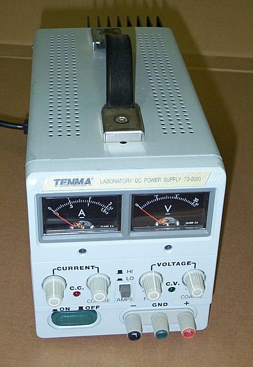
You will need a small Variable Voltage Laboratory Power Supply with Build-in Voltmeter
and Current Meters. I use this Model that puts out up to 40 Volts DC at up to 3 Amps.

This page was last updated: February 9, 2026
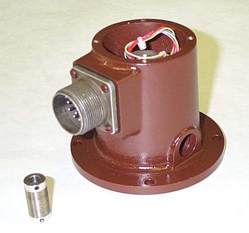
This is the #17546-000
Resolver Feedback Package.
Why Pay Strippit 3 Times our Price
for The Same Part?
Where to Buy It is Kind of a
No-Brainer, Don't You Think?
Update. Strippit does Not even have Feedback Packages Anymore!
We have Lots of them!
And Don't Forget the
#17648-000 Resolver Coupling.
Couplings are Often Broken
by Bad Resolvers.
11 --- Make sure a 8 Foot Ground Rod was put-in All-The-Way into The Ground!
And is firmly attached to the Ground Strap hanging under Machine's Control Cabinet.
12 --- Many FC1000/3 Machines have been Moved and were Never Properly Reinstalled.
If not properly installed, there is excessive Vibration which I have seen shake Transistors
right off a Servo board! Excess Vibration can & will cause many Control & Servo Failures!
-- The Machine Must be Level, with equal Pressure on all 6 Barry-Mount Rubber Feet.
-- The 4 Shipping Bolts in Servo Cabinet, and 4 Bolts in Control Cabinet must be Removed.
-- The Bolts on the Cross-Bar between Cabinets must be Removed.
-- The Feet under the 2 Cabinets must be Lowered to the Lift Cabinets a bit,
so Cabinets "Float" on the Rubber Mounts attached to Machine Frame.
For Hi-Tonnage Punching, there is a Much Better way to Mount the Machine using "Jake Bolts"
and Epoxy Machine Grout, which is how Strippit Mounts Machines now to Reduce
Shock & Vibration, and Improve Machine Reliability. We can provide details if needed.
Note, There is More Information on Proper Machine Installation
on Our "Bubble Memory Problems" Web-Page.
13 --- Test that the X & Y Slow-Down and Limit Switches are Working Properly.
These Switches Protect Machine Mechanical Parts and Electronic Servo Drives from Damage by
Preventing Hard "Crashes" at End of an Axis's Travel. As an Axis approaches it's End of Travel
in the High-Speed Mode, it should Engage "Slow-Down" Switch or Sensor forcing Axis to Shift
to "Slow" Mode. If you Persist in Moving Axis toward End of Travel, you should next Engage
"Limit" Switch or Sensor, which should Generate an "All Hold" Condition and
Shut-Down the Servo Drives, and Axis should Stop a Couple of Inches before it would have Hit Something at the End of it's Travel. Check this every 6 Months, for Both Directions in
Both X and Y Axis. Promptly Repair any Problems found.
14 --- Tune the Servo Drives a Little "Softer" with a Little Less Gain. This causes Servo-Drives
and Servo-Motors to Require Less Current, with the Result that they Fail Less and Last Longer.
Strippit Manuals and my Old Servo Manual say to set X & Y Following-Error to about 330 usec.
when making 30 inch moves.
I Now Set X & Y Following-Error to about 380 to 400 usec. when making 30 inch Moves.
This requires Oscilloscope and Technician that Knows what he's doing.
I set T-Axis Following-Error at 380 to 400 usec. while Homing the Turret Axis.
I usually have "Max Speed" Pot on PWMC Boards turned All the way Down for Minimum-Gain.
Note! The Adjustment Direction on This Pot is Counter-Intuitive,
as you have to Turn Pot CLOCKWISE to Reduce the Gain!
I Usually Turn Max Speed Pot All The Way Clockwise and Leave It There!
15 --- Make sure Fan at Bottom of the Servo Drive Units is Running, and is Blowing Air Up through
Aluminum Heat Sinks! These Fan Motors Seize-Up in old age. We Stock Replacements!
16 --- Tooling is Critical! Dull Punches & Dies, Wrong Die Clearances, Miss-Adjusted Holders,
and Just Plain Worn-Out Tooling will Cause Stuck-Punches, Failure to Strip, and Slug Pop-Ups
that will Not Only Ruin your Part-Sheets, But will Also Tear Up Mechanical Parts on your Machine.
And can Blow-Up Servo Drives Electronics when Axis are Jammed!
Junk-Tooling Will Not Work In a HI-Speed Punch Press!
Caution! Caution! Caution!
Do NOT Ever Reach-In, Get On-Machine To Lube,
Move Workclamps, Or Work On The Machine For Any Reason,
With The Machine On!!!
Always Turn The-Control Off!!!
If a Control or Machine Failure Should Occur,
Axis Could "Run Away" And Cause Injury Or Death!!!
7 --- Electronics Do NOT Like Heat or Cold!
Strippit Air-Conditioned CNC Control-Cabinet, But Not Servo-Cabinet! I Would Seal-Up
Servo-Cabinet, and Mount a 4000 BTU Control-Cabinet Air-Conditioner, from Kooltronics
or McLean Co's., to The Swing-Out Servo-Cabinet Door!
These are Special Air-Conditioners Made to Easily Mount onto CNC Machine Cabinets,
recirculates the Air to Keep Out Humidity and Dirt, and will Not Spray Water into Cabinet.
Do Not Even Think about trying to adapt a cheap Window Air Conditioner to Servo-Cabinet!
Maintain Servo-Cabinet Air Temperature at 70 to 75 Degrees Fahrenheit.
Make sure Control-Cabinet Air Conditioner is Keeping CNC Control at 70 to 75 Degrees.
Electronics Do NOT Like Cold!
Many Shops in the North Turn-Off Heat at Night in the Winter. Next Morning Shop may be
as cold as 30 or 40 Degrees Fahrenheit! CNC Controls are Industrial Grade Electronics,
Not Military or Aero-Space Electronics, and they Will Not Reliably Work Below 50 Degrees!
I often see Power Supplies Fail, Bubble-Boards Lose Memory-Data, Servo-Drives Blow-Up,
and Oils & Greases in Machine Too Thick to Flow Correctly! This is for All Machines,
Not just Strippits! Do NOT Turn-On your Machines Until it has Warmed Up to 50+ Degrees!
8 --- Capacitors go Bad with Age, and can cause Servo-Drives Failures.
We Replace Bad Capacitors also Up-Size certain Capacitors for Greater Reliability.
All 3 of the PWMC7 & PWMC8 boards Should be sent-in to us, and
we can Up-Date them with only 2 day Turn-Around Repair time.
The PSRG3 or PSRG5 Power Supply board should also be Updated
with New Caps., and we can also Retrofit a Better MVR-Relay to Improve Reliability,
and Add a LED-Indicator Light to Signal when the Relay is Pulled-In or Not,
which greatly helps in Troubleshooting Servo On & Off Problems.
9 --- Make sure Ballscrews & Guide-Bars are Clean, Well Oiled, and in Good Condition.
A Bad or Worn Ballscrew or Guide-Bearings can add a lot of Mechanical Drag on the
Servo-Drive which can Stress & Fail them.
Also, The Axis Lube System Does Not Work On Many FC1000/3 Machines because of a
Control Software Bug, and Failures in the Lube-Drive Hardware. Do NOT Depend On It!
Its Best to Lube X & Y Axis Ballscrews by Hand Every Day!
Use a Coffee-Can with the Same "Mobil DTE "Heavy" ISO 100" Lube Oil that you are
using in the Press-Drive Lube Tank, and using a 2" Wide Long-Handle Paint Brush,
Paint Both Ballscrews and Thomson Guide Bars with this Oil.
Do This Every day!!!
6 --- Check Resolver-Feedback Packages.
I would do this once a year, every year, for both X & Y Axis.
When Resolver-Feedbacks Fail, Axis will Run-Away, and could Slam into End of Carriage,
possibly Damaging Axis Guides, Ballscrew, and Blowing the Servo-Drive.
Take Package off, and Spin Small Resolver-Shaft between your fingers.
It should Spin Very Smooth. If Rough, or if there is a lot of Side-To-Side Play, or
a lot of End-to-End Play, Replace Package. Axis will need to be Rezeroed when Reinstalled.
Do NOT Take Your Bad Servo Motor To The "Local" Motor Shop!
These Shops Are Set-Up To Rewind A.C. Electric Motors Only
And Can NOT Handle D.C. Servo Motors!
They Usually End Up Damaging Servo Motors Further
As They Try To Figure Out how to take Motor Apart!
Then They Badly Cut-The-Commutator, Install New Bearings, Paint It,
and Declare That It's "Rebuilt", When In-Fact, It's Still Burnt-Out!
Because Of Problems Trying To Get Servo Motors Properly Repaired,
I Started Rebuilding Them Myself 30+ Years Ago.
Every One Of Our Motors Is
Tested-Good On a Actual Strippit Machine After It's Rebuilt!
We are The Only Company that Test Motors on a Strippit CNC Machine.
We Now Keep All Strippit DC Servo Motors In-Stock For Quick Shipping
Here is a Picture of
Fab Metal's (Knoxville, TN)
FC1000/3 Machine,
which is Factory-Wired
for 230 VAC,
that we have added;
2 --- 1.5KVA Acme Electric Corp.
Cat. #T-1-11684
Boost-Buck Transformers
to get the
Whole Machine Voltage
Correct at 225 VAC.
And we have
Never had a Servo Problem
with this Machine!
1 -- Remove Center-Part of Motor Coupling so that
Motor can spin freely.
2 -- Un-Hook 2 Motor Armature wires from the Servo Drive.
3 -- Turn Power Supply On.
4 -- Turn the Power Supplied's Voltage down to Zero.
5 -- Hook Power supplies leads to Motors Armature Wires.
6 -- Slowly turn the Voltage up to 30 Volts D.C.
7 -- A Good FC1000/3 X-Motor
will draw About 1.0 to 1.1 Amps.
Good FC1000/3 Y-Motor will draw About 1.0 to 1.5 Amps.
Good FC1000/3 T-Motor will draw About 0.6 to 0.7 Amps.
And Motors will run Smooth and Quiet.
8 -- A Bad Motor will Try to Draw Too-Much Current, and
will put my Power Supply into its Current Limit Mode
at over 3 Amps, and Motor will Not even turn!
9 -- A Bad Motor will often Have a Noisy, Rough, Burnt,
and Out-Of-Round Commutator. Replace Bad Motors!
FC1000/3 Press Drives are Quite Reliable, but are not trouble free.
They "Punch Too Fast" in My Opinion, which leads to Tool Stripping Trouble if your Tooling is not kept in Excellent Condition, with proper Die Clearances, Etc. The Fast Press Speed also leads to Rapid Clutch & Brake Wear, Splin-Hub Wear, Flywheel Bearing Wear, and Stress on Crankshaft.
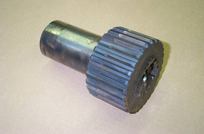
Stress on your Crankshaft,
Kind of Looks like This.
Crankshafts Always Break at the
Inside of Brake Splin Hub.
Strippit used Many Different Versions of Crankshafts, and
is Usually Confused about Which Version you should have in Your Machine, and they Probably will Not have one anyway.
It is Expensive & a Lot of Work to Replace with a New Crankshaft.
We have Successfully REPAIRED
several Broken Crankshafts. It is
also Expensive & a Lot of Work.
One of the Best Ways to Reduce Wear & Tear on Press Drive, as well as being Cheap & Easy
(You Do Like Cheap & Easy, Don't You?)
is to Slow-Down the Press Drive Speed, and Therefore the Punching Speed.
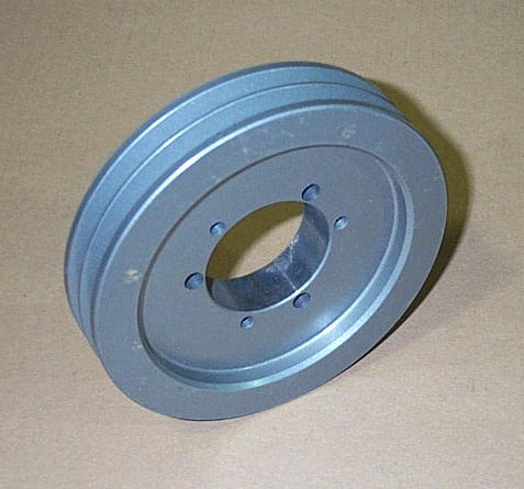
We do this by simply changing the
Press-Drive Motors Shive (Pulley).
The size we use Slows the Up & Down
Punching Speed about 10%,
and you will Not even notice it!
But it Greatly Reduced Stress and Wear on
All the Press-Drives Components, and helps cure many Tool & Punching Problems like
"Slow-Strip", Stuck-Punches, & Slug Pop-Up.
Most Original Shives were 6.0" Diameter,
but Strippit did use some other Odd Sizes.
We Recommend Doing This To All
FC1000/3 Machines and To All
FC1250/30/1500 Machines
With 33-Station Turrets!
We can Provide the Proper Shive
for your Strippit Machine!

We have Many Other Recommendations
on how to Improve your Press Drives Reliability
on our WEB-PAGE
COMMON STRIPPIT MACINE PROBLEMS
Please "Click-On"
The Button to the Right to go there.


Machine Technologies Co.
Strippit Machine Repair-Parts
&
Strippit Machine Repair-Service
Phone 704
233-5229
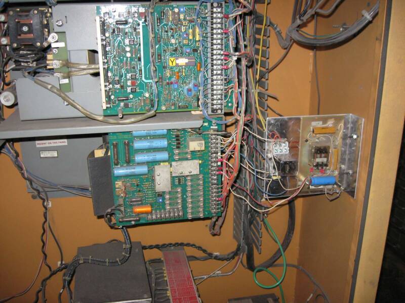
Above is Select Stainless Co's FC1000/3 Machine, in Downtown Matthews, NC.
Their Machine was wired 460 VAC, but their Power was about 486 Volts AC, Too High!
On this Machine, Prior-Owner had Fitted a Large 120 VAC Control Transformer
(on Back of Control) to also run their Slug-Conveyor. This left lots of room next to the Big Servo Transformer to Mount 3 small Buck-Transformers shown on the Right.
NOTE! It is NOT Necessary to Reduce Voltage for the Whole Machine, so we reduced
it to Just The Servo Transformer. We used 3 Sola Hevi-Duty Model E500D
.5KVA 240 / 480VAC to 24VAC Transformers to do this, they only cost $74.00 each.
Before Transformers;
AC Voltage to Servo Transformer 486, Servo DC Buss Voltage 170, Too-High!
After Buck-Transformers was Added;
AC Voltage to Servo Transformer 449, Servo DC Buss Voltage 154, Just Right!
3 --- Check Control AC Voltage.
In the Servo Cabinet, 2 of the 3 Power-Phases are Picked-Off for the Control Step-Down Transformer to Generate the 120 Volts AC that Powers the CNC Control.
I Like this Voltage to be 115 to 125 Volts AC.
If it is Higher or Lower, have a Technician Adjust Change Transformer Taps to Fix it! It is Very Important that the Control Voltage be Correct, or this could cause all sorts of Various Intermittent Control Failures! Strippit Got Cheap, and Some Machines do Not have a Transformer with Proper Over & Under VoltageTaps, these Machines would need to have Transformer Replaced.
PRESS DRIVE PROBLEMS
Strippit FC1000/3 Turret Punch-Press Machines with the HECC80/3 Type Controls are Popular
as they are Extremely Fast, Accurate, Very Easy to Operate, and Easy to Move & Install.
About 250 of these Machines with HECC80/3 Controls were built in the years 1981 to 1986,
and this Web-Page deals mainly with these HECC80/3 Versions.
After 1986 Strippit changed to Fanuc CNC Controls & Servo Drives, and continued to make more of these fine Machines with GN6 Fanuc Controls & Drives. Machine Technologies Speciality is the HECC80 Control Machines, and we Mainly Deal with HECC80 Controlled Machines. However,
many Mechanical Parts on Fanuc FC1000/3 Machines are the Same as on Earlier HECC80 Machines,
so we Do have Many Repair Parts Available for Fanuc Control FC1000/3 Machines.
Like All Machines, New and Used, they had some problems.
The most common problems were with the Servo Drive and Bubble Memory Board.
I have a Separate Web-Page on the Bubble Memory Board Go There for Its Problems & Fixes!
We have Learned Much about these Problems over the Years, and I will share Some of our Solutions.
But it's up to YOU to Implement These Solutions.
I Don't Want To Hear The Stupid
"Well, It's Run OK like that for Years"
Excuse for Not Doing Them!
If You Don't Do Them,
Do NOT Complain To Me when I Tell You Costs to Repair!
FC1000/3 SERVO DRIVES
Breaking Your Crankshaft is one of those "Bad Things" that you should try Very Hard to Avoid!

10 --- Tighten All Connections!
Turn off AC Power, and have a Good Technician Pull-Up-A-Chair, and go through the Whole
Servo Cabinet, and Firmly Tighten Every Single Nut and Screw in Servo-Cabinet!
Then, Go to Other Side of Machine, and Tighten Every Screw in Control-Cabinet!
Over time,Temperature Changes & Vibration will Loosen-Up Connections which will Start Arcing.
Pay extra attention to Servo-Rectifier and Filter-Capacitors in the Servo Power Supply
section of Servo-Drive, as I often see a lot of Arcing and Burnt-up Parts there.
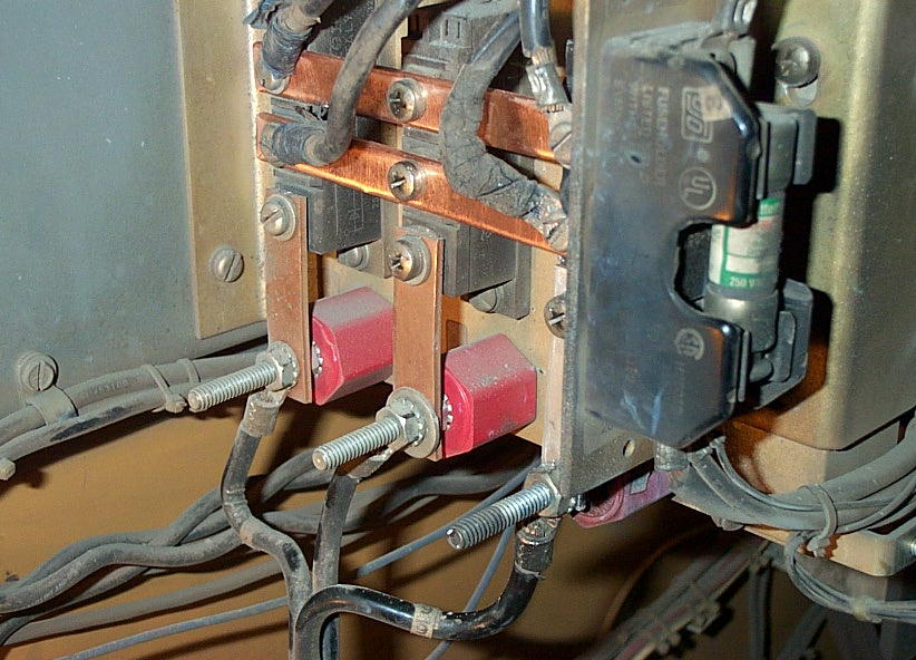
A Very Common Problem on a Rectifier Assembly on a Model 3A Servo.
There are 3 Rectifiers with 2 Large and 3 Small Buss-Bars Connecting them to the
AC Inputs and DC Outputs. Over time, the Screw Connections get Loose,
then start Arcing and Burn-Up Rectifiers and Buss-Bars.
We had to replace 1 Rectifier and make 4 New Buss-Bars to Repair this Assembly.
Keep Screws Tight! Tighten Yearly, during your Preventive Maintenance Week.
Yeah, I Know, You Don't Do That......
We have Other Recommendations on how
to Improve your Servo Drive Reliability
on these 3 WEB-PAGES
SERVO DRIVES
SERVO-DRIVE REPAIRS
SERVO-DRIVE MOTORS
Please "Click-On" The Buttons
to the Right to go there.


2 --- Check that the Regen Circuit is Functioning Correctly!
When a Servo-Motor Decelerates, it becomes a D.C.-Generator with all the Axis Momentum being Converted into D.C. Power that Backfeed's into the Servo Drives Power Supply.
This causes the Servo Power Supply Voltage to Rise, and if it gets Too-High,
it can Blow-Out the Servo Drive Modules and Boards, Just like in Discussion #1 above!
The Regen Circuit Senses this Hi-Voltage, and at about 182VDC, it Turns-On,
and Dumps this Excess Power into Load-Resistors until the Voltage Falls to about 178 VDC.
Unfortunately, this is Not-Easy to Check, and I Do Not know of other Technicians besides myself
that can do this. I have several different Test Procedures for these Circuits. One I use is to Monitor the D.C. Servo Power Supply, and Catching & Seeing this Regen Turning On & Off, with my Digital
Tektronix Oscilloscope, on a Strippit FC1000/3 Machine when making 30 Inch Y-Axis Moves.
FC1000/3's below #066 usually have the "3" Servo Drive that does Not work well,
and uses the PSRG3 Regen Board and SCR's that are Very Hard to Test and Repair.
FC1000/3's above #066 have Improved "3A" Drive that does works well, and I have a Very Good
Test-Station here in my Electronics Lab to Test and Set-Up the PSRG5 Regen Board.
There are Too Many Variables to discuss here, but Regen Board should be Checked to see it Turns
On & Off at Proper Voltages, All Fuses are Good, and Regen Load Resistors are Not Melted!
The PSRG5 Regen Board Can be Sent-In to Machine Technologies for Set-Up and Up-Dating.
To Recap,
Do All The Recommended Procedures
To Reduce Expensive Machine & Control & Servo Drive Failures!
1 --- Reduce incoming Servo A.C. Voltage to 230 / 460 Maximum
to Reduce the DC Servo Drive Buss Voltage to about 155 VDC!
2 --- Make Sure Servo Drive Regen Circuit is Working!
3 --- Make Sure Control AC Voltage is Proper 115 to 125VAC !
4 --- Reduce X & Y Axis Speed with a F2 or F15 Feedrate in All Your Part Run Programs!
5 --- Service Servo Motors Regularly! Check Brushes, Springs, Armature, Commutator.
6 --- Inspect Axis Feedback Packages Yearly, and Replace Worn Packages!
7 --- Add Air Condition to Servo-Cabinet!!!
Maintain Control-Cabinet AND Servo-Cabinet Air Conditioner 70 to 75 degrees!!!
8 --- Send-In PWMC7 & PWMP8 Boards to be Updated with New Capacitors!
9 --- Oil Guide Bars and Ballscrews!
10 --- Tighten All Connections in Servo & Controls Cabinets!
11 --- Install a Good 8 Foot Ground Rod!
12 --- Properly Install Machine & it's 2 Cabinets!
13 --- Check all Axis Slow-Down and Limit Switches!
14 --- Retune Axis Servo Drive "Gain" to Reduce Servo Drive Stress!
15 --- Make sure Servo Drive Fan is Working!
16 --- Change Press-Drive Motor Shive to Reduce Axis "Jam-Ups"!
17 --- Use Only Sharp & Properly Adjusted Tooling with Correct Die Clearances!
18 --- Never Even Turn-On Machine and CNC Control if Shop Temperature is Below 50 Degrees!!!
If You can't be Bothered to Invest some Time & Money to help keep your
Critical Punch Machines Running, don't Cry to Me when they go "Down".


More Servo Motor Information
is on This New Web-Page, Take A Look!
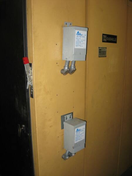
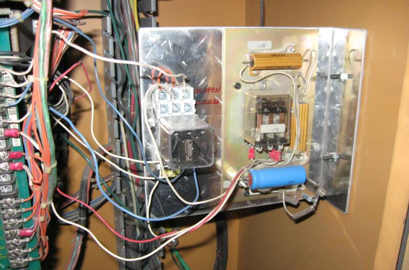
Above is another Strippit HECC80/3 Control FC1000/3 in Downtown Matthews NC.
Machine was wired for 460 VAC, but their Power was about 486 Volts AC, Too High!
NOTE! It is NOT Necessary to Reduce the Voltage for the Whole Machine!
So we decided to reduce A.C. Voltage to Just the Servo Transformer.
We Mounted 2 small Buck-Transformers, as shown, on the Back of Servo Cabinet.
We used 2 Acme Electric Co. Catalog #T-1-81065
.5KVA Buck/Boost 240 / 480 VAC to 24 / 48 VAC Transformers to do this.
If this was a 230 Volt Factory Wired Machine, Amperage requirement would Double,
so we would use 2 -- 1.0 KVA Transformers instead of the 2 -- .5 KVA
Acme has Much Online Information on Using & Wiring Buck/Boost Transformers in
their Online Catalog at www.acmepowerdist.com Go Check it Out!
Before Transformers;
AC Voltage to Servo-Transformer 486, Servo DC Buss Voltage 170, Too-High!
After Buck-Transformers was Added;
AC Voltage to Servo-Transformer 439, Servo DC Buss Voltage 150, Perfect!
The above 3 Customer's have done Everything we told them to do to Increase Reliability,
as noted on This Web-Page, such as;
---- A.C. Servo Buck Transformers to Lower the Servo DC Buss Voltage to about 155 VDC
---- Updated PWMC7 & PWMC8 Servo Drive Boards
---- "Retuned" PWMC7 & 8PWMC Boards for Less Gain & Servo Stress
---- Reduce X & Y Speed by adding F2000 Feedrate to All Their Part-Programs
---- Change Press-Drive Motor Pulley for slighly Slower Punching Speed
---- Installed Heavy-Duty Lifter Springs for Better Tool Stripping
and they have ZERO Servo Problems!
Luckily for Me, Most Customers do Not do these Updates, so I do a Brisk Service & Repair Parts
Business with them, and I can keep ahead of my Wife's Spending. The Choice is Yours!

If I don't Answer the Phone,
it's cause I'm Out Traveling,
Leave A Message!
We had a Pretty Good Apartment Location Here,
Don't you think?
Hint, that's the Back of The Louvre on Right,
The Seine River on Left,
and some Old Tower in the Middle.
You Should See It at Night!
17 --- Intermittent Servo Inhibits.
Once or Twice a Year, I see a FC1000/3 that the Control thinks everything is OK with No Error Messages on the CRT Display. This Condition could be Intermittent, or could be Constant.
If you grab X or Y Ballscrew you can Easily Turn Them Proving that the Servo Drive is OFF, but
Control does Not know it! It you try to Move X, Y, or T Axis, they will Not Move and you get a Excess Error Message, which means that Axis is Not where Control thinks it should be.
This is Usually caused by an Internal Inhibit caused by RL1 Relay Contacts 4 & 7 being Closed,
but Contacts are Old & Corroded, so that "R-Inhibits" from X, Y, & T TB302-R Terminal Strips
are Not Pulled-Down to Ground because of Bad Connection between 4 & 7 Contacts.
You can Easily Check this by Monitoring Voltage at X or Y TB302-R Terminal.
D.C. Voltage --- Less that 1 Volt, The Normal Servo-On Un-Inhibited Condition.
D.C. Voltage --- About 7 to 8 Volts, RL1 Relay is Not Pulled-In, The Servo is Off & Inhibited.
D.C. Voltage --- Voltage Drifting around from 1 to 8 Volts, Caused by Dirty or Corroded RL1 Relay
Contacts, and The Servo Drive may Turn On & Off and Work Intermittently.
Unfortunately, G.E. Buried this RL1 Relay Behind PSRG Board where you Can Not Get to it, or
even see it! They also used an Odd Type Relay that is Bolted Directly to Panel, and has Stake-On
Terminal Wire Connections, not a nice & easy Relay Socket so that you could Plug-In a new relay.
So, to Repair, I replace with a different Type of Relay (Grainger #1A488 Relay & #5X853 Socket) and I use a Relay Socket so it can be Easily Replaced. I Also make a L-Bracket (You are in a Sheetmetal Shop after All!), Cut all the Wire-Ties, and Relocate this New RL1 Relay & Socket,
and the Related RL3 Relay Panel, to a Place where I can Easily See and Work on it.
Problems with RL1 & RL3 Relay Circuits can also cause X, Y, T Servo Contactors from Pulling-In.
CNC Controls will Not "See" This, so there will be No Servo Error Messages when "Message" Softkey is Pushed. Test this by "Pushing" X & Y Axis by Hand, if you can Push the Axis, your Servo-Drives are Not-On, and this is probably caused by an Inhibit Problem or Contactor Problem.
Note! This is Tricky-Work, and Should Only be Done by a Experienced Technician who Also Has Actual G.E. Servo Manuals as a Guide, as G.E. Wired these Panels Several Different Ways and
Wiring Mistakes could be very Costly! I have some Servo Manuals still In-Stock & Available.
On Occasion, I have had 1 of the 1/4-Amp. Fuses on PSRG5 Servo Board Blow from old-Age,
which can also cause this Servo-Off Problem.
Check all Fuses and that the Correct DC Voltages are Present on the TB201 Terminals.
A Burned-Out Contactor Coil is also a Very Frequent cause of No Servo Drive with No Messages.