Strippit Houdaille HECC80/1 Control
Circuit Board Types & Usage
Note #1. Strippit Houdaille Circuit Boards have 2 Numbers on them. The "Odd" Number is for a Raw-Blank Circuit Board with No Parts on it, and is of No Interest to You or Us. The "Even" Number is for a Finished Assembly Circuit Board.
Example, the "Odd" Number #400635-xxx is for a Blank CPU Circuit Board. We are Interested Only in the "Even" #400636-xxx Finished Assembly CPU Board Number.
Note #2. Many Early Circuit Boards were Poorly-Marked or Not-Marked Correctly at All.
Also, Many Board-Types were Modified & Changed & Swapped in the Field, and the New Dash-Number (-xxx) Type was Often Not Updated, Leading to Much Confusion.
Note #3. Strippit Made Many Different Versions of some of these Boards that are Very Similar, But are Not The Same! Pay Attention to the ( -xxx ) Dash Numbers at the End!
Note #4. HECC80/1 & HECC80/3 Type Circuit Boards Are Very Similar, But Are Not the Same! If You have More than 1 HECC80 Control Machine, Do Not Mix up the Boards!
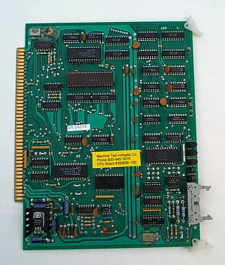
CPU Board
#400636-100 Standard CPU Set-Up for
20-ma Current-Loop Interface
#400636-232 Standard CPU with RS-232 Interface
Comes in above 2 Types. The Only Difference is the -100 Type can Interface to Defunct Teletype ASR33 Printer/Punches (which I have seen used once in 29 years!) and the -232 Type can Communicate to P.C. Computers through it's RS232 Port.
The -100 Type can be Converted to the -232 Type.
CPU Boards are Only Used in Cardcage Slot #2.
The CPU is the "Brain" of the Control,
if it's Not Working, Nothing Will Work!
In Normal Operation, the CPU Board has
2 Green-LED Lights "On" & 3 Red-LED Lights "Off".
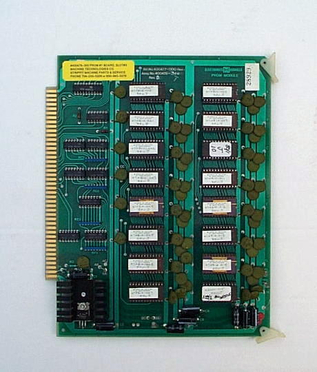
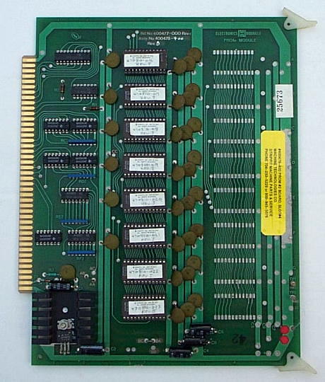
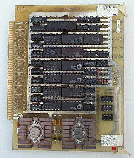
Prom #1 & Prom #2 Boards
Sets of 2 Prom Boards Store the Executive-Run Program that Runs Control & Machine. Prom 1 Board
goes in Slot #3 & Prom #2 Board in Slot #4.
Here are a Few of Many Versions of these Boards;
#400478-300 HECC80/1 Prom #1
#400478-400 HECC80/1 Prom #2
#400478-422 HECC80/1 Prom #2 LaserTool Option
#400478-320 HECC80/102 Prom #1
#400478-420 HECC80/102 Prom #2
#400478-424 HECC80/102 Prom #2 LaserTool Option
#400478-350 HECC80/28 Prom #1 LaserTool
#400478-450 HECC80/28 Prom #2 Lasertool
#400478-370 HECC80/28 Prom #1 Turbo-Lasertool
#400478-470 HECC80/28 Prom #2 Turbo-Lasertool
#400478-700 HECC80/750 Prom #1
#400478-800 HECC80/750 Prom #2
#400478-720 HECC80/752 Prom #1
#400478-820 HECC80/752 Prom #2
Special Information, like Machine Type & Size,
Options, Etc., were Programmed into Chip #15.
Prom Board Failures usually cause "Check Sum Error" at Control Power-On, and Red-LED Lights on CPU after
Control is Running. We Can Repair Prom Boards,
and Can Add Options Like RS-232 Downloading.
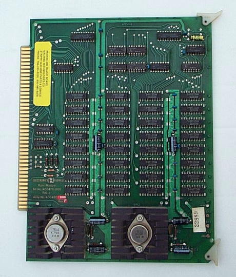
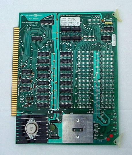
Ram #1 & Ram #2 Memory Boards
Your Part Programs are Stored in these Ram Memory 2-Board Sets.
Ram #1 goes in Slot #5, and Ram #2 in Slot #6.
#400480-000 Standard 16K-Memory Ram #1
#400480-400 Standard 8K-Memory Ram #2
#400480-008 Special 12K-Memory Ram #1 for HECC80/28 Lasertool Controls Only
This is a Listing of
Types & Usage
of Electronic Circuit Boards in Strippit Houdaille
HECC80/1 Type CNC Controls.
These CNC Controls were Used on Strippit CNC Turret Punch Press and Laser Machines
Built in the 1970's & 1980's.
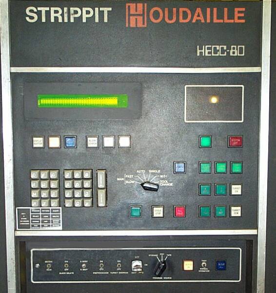
HECC80/1 Type Control Panel
Looked like Picture at Right.
If Your Control
Does Not look like This Control, Then go to Our
Web-Page and
Properly Identify
YOUR CNC Control Type!
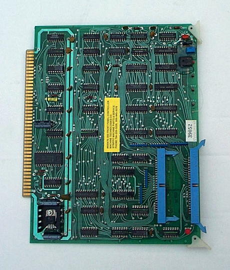
Front Panel Controller Board
#400476-000 Front Panel Controller, Slot #7
This is the Board that "Talks" to All the other Parts on the Control Front Panel (the Door).
Like the Self-Scan Display, Tapereader,
and All the Control Panel Switches & Knobs.
If You are using a M81 Post Punch Delay Programming Code, the Control Looks at the Switch Position on this Board to Determine if you want a 100 MSec. Delay (Switch Down)
or a 250 MSec. Delay (Switch Up).
When Replacing this Board,
Try to Insert 2 Ribbon Cables Correctly
( Brown Wire is Always "UP" )
and Try to Put Cables in the Correct Slot!
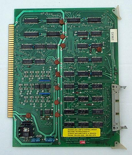
Lamp & Control Driver Board
This Board Originates Commands for all Solenoid Drives for Machine and all Control Front Panel Lights. Board goes in Slot #8.
There are 3 Non-Interchangeable Board Types;
#400464-000 The Original Early-HECC80 Type, used Only with Small #400504-000 Solenoid Driver Board Located in Top of Servo Cabinet.
#400464-200 Improved HECC80/1 Type. Connects through a Ribbon Cable to #400790-100 Output Isolator (Solenoid Driver) Board Located in the Back-Side of Control Cabinet. This Board also has Improved Anti-Punch Circuitry so that it Won't Punch when CPU Board Loses it's "Mind".
#400464-300 Used in FC750 and FC750/2 Machines,
also Drives a #400504-000 Solenoid Driver Board.
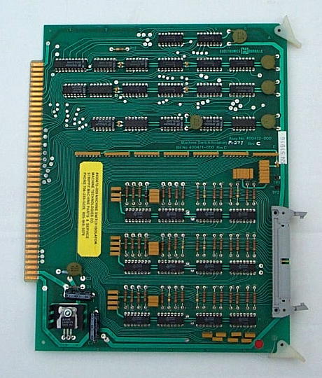
Machine Switch Isolator Board
#400472-000 Machine Switch Isolator Board,
1 Type for All HECC80/1 Type Controls, Slot #9.
All the Switch-Signals on the Standard Machine Return to the CNC Control through this Board.
One Chronic Problem with this Board is that after Many Years & Thousands of Hours of Use, the Opto Isolator Chips used on this Board Actually Grow-Weaker and Wear-Out.
This can Cause False Switch Signals, and the Board will Need to Rebuilt with New I.C. Chips.
We, of Course, Can Do this Testing & Repair.
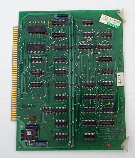
Axis Control Board
#400470-000 Axis Control Board
only 1 Type made for All HECC80/1 Types.
3 Boards per Control are Used;
1 in Slot #12 for X-Axis
1 in Slot #13 for Y-Axis
1 in Slot #14 for T-Axis
These Boards Hold and Execute each
Axis Move as the CNC Control issues each Program Move to it.
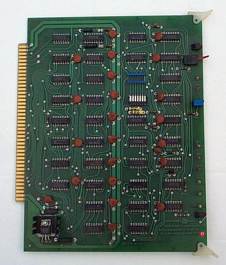
Position Comparator Board
3 Types were Made;
#400474-000 First Type used with 2-MHZ
Square-Wave Resolver Excitation Board Systems
#400474-200 Second Type, Removing Capacitor
C1 makes it a -200 Board used with 3-MHZ Square
or Sine Wave Resolver Excitation Board Systems.
#400474-300 Third & Last Type. No C1 Capacitor.
Resistor R4 changed to 75K to allow more Punch
Anticipation for Faster Punch Rate. Mainly used
with 3MHZ Sine-Wave Excitation Board Systems.
3 Boards used per System, X in Slot #15,
Y in Slot #16, and T in Slot #17. These Boards Compare Command Position from Axis Board & Actual Resolver Feedback Position then Generate
a Error Signal to Phase Analog Board.
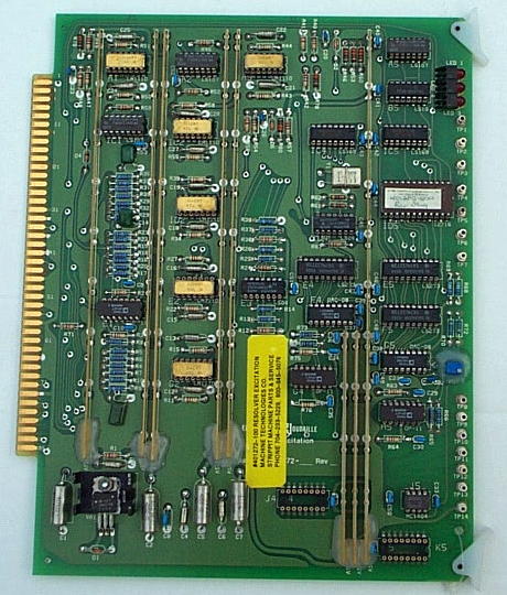
Resolver Excitation Boards
These Boards make Sine and Cosine Excitation Signals for Resolvers Located in Feedback Packages on End of each Axis Servo Motor.
Boards go in Slot #19.
3 Types of these Boards were Made;
#400468-000 2 MHZ Square-Wave Type. Used on Early HECC80/1 Controls. No Crystal on Board.
#400468-300 3 MHZ Square-Wave Type.
Has On-Board Crystal to Provide 3-MHZ Signal. Frequency was Increased to Improve
Servo Response and Better Servo "Tuning".
#401272-100 3MHZ Sine-Wave Type. Output Waveform is Sine-Wave instead of Square-Wave
of Older Boards. This Board Greatly Increased Positioning Accuracy that Laser Machines Showed
was Lacking in Older Square-Wave Types.
Note, These 3 Boards are Not Interchangeable! However, Machines with Older Type Boards can
be Changed to Newer Type Boards to Improve Accuracy, but Does Require some
Rewiring of Control Cardcage.
Late HECC80 Controls came from Factory with
3-MHZ Sine-Wave Boards, and some Controls
were Retrofitted In-The-Field to this Type to Improve Accuracy. Be Sure what you Have!
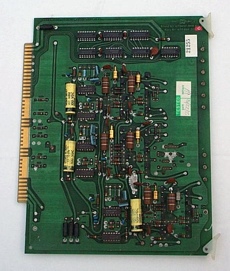
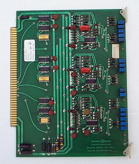
Phase Analog Boards
Many Different Types, Sometime Machines have the "Wrong" Type Board in Control, but still will Run OK.
#400482-000 Early FC1250/30/1500 Machines using
2 MHZ Square-Wave Resolver Excitation Boards.
#400482-100 Early FC1000/2 and FC750 Machines using 2MHZ Square-Wave Resolver Excitation Boards.
#400482-200 Early FC1250/45 Machines using 2 MHZ Square-Wave Resolver Excitation Boards.
#400482-300 FC1000/2 Machines using 3 MHZ Square & Sine Wave Resolver Excitation Boards.
#400482-301 FC1250/30/1500 and FC1250/45 Machines using 3 MHZ Resolver Excitation Boards.
#400482-30A Some kind of 3MHZ Rebuilt Board ???
#400482-600 FC750/2 & FC750 Machines with
"Nibble-Drift Retrofit" to Improve Contour Nibbling.
Uses 3MHZ Sine-Wave Resolver Excitation Board.
Phase Analog Boards (Slot #18) take Digital Position Error Signal from Position Comparator Board and Converts it to a Analog Signal for the Servo Drives. Potentiometers allow each Axis to be "Tuned" for
Variations of each Individual Machine.
Continuous Contour Board
#400888-000 Continuous Contour Circuit Board.
Board goes in Slot #10, and allows
Smooth Continuous Motion in X and Y Axis
that is Required by
Laser Cutting and Plasma Cutting Machines.
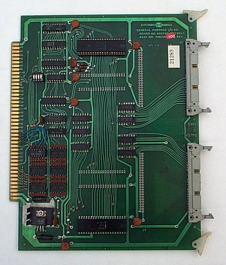
General Purpose I/O Board
#400790-100 General Purpose Input Output Board
Used on Machines with Load / Unload Systems
and Lasers Machines to Handle
Extra I/O Switch and Driver Requirements.
Connects by Ribbon Cables to the
#400788-xxx Input & Output Isolators Boards.
Goes in Slot #21.
Input & Output Isolator Boards
#400788-000 13-Output (Solenoid Driver) Isolator
Board used with #400464-200 Type
Lamp & Control Driver Circuit Board.
#400788-100 24-Output (Solenoid Driver) Isolator Board used with #400790-100 General Purpose I/O Boards. #400788-100 24-Output Board May also
be Substituted for #400788-000 13-Output Board.
#400788-200 24-Input Isolator Board.
Provides 24 Opto-Isolated Inputs to Control for
Load / Unload and Laser Machine Switches.
Solenoid Driver Boards
There are 2 Versions of this Board.
#400504-000 Solenoid Driver Board.
Used on the Original HECC80 (NOT HECC80/1) Controls that used #400464-000 (Not #400464-200) Lamp & Control Driver Circuit Board.
This Type Driver Board was also used on
All FC750, FC750/2, and FC75/30 Machines.
#400504-200 Solenoid Driver Board.
Used on the NC "A" Control Machines
and T-SAF30 Machines.
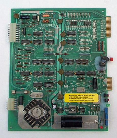
Master Monitor Boards
These Boards have 2 Functions;
1 -- This Board is Always On as It Starts-Up Control & Machine when You Push System-On Button.
2 -- It Monitors (With Slave Monitor Board) All of Control & Machine D.C. Voltages.
If 1 of the Voltages is Too High or Low, it will Shut-Off Control about a Second after Turn-On.
This is The Most Common Control Problem and is Caused by Either A Short-Circuit in Control or Machine, or a Bad Power Supply Board.
By Testing the 16 Test-Points on Both Master & Slave Boards, you can See which Power Supply they Did Not Like and Caused Shut-Down.
Goes in Slot S2, There are 2 Versions of Board;
#400536-000 Standard Monitor Board.
#400536-500 Standard Monitor Board, Except
Jumper #5 Has been Removed so it does Not Monitor for the +250VDC Supply when New-Style Display Retrofit has been Installed which
Requires that +250 VDC Supply be Disabled.
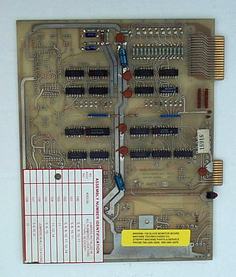
Slave Monitor Boards
It Monitors All of Control D.C. Voltages
(with the Master Monitor Board). Goes in Slot S1.
If 1 of the Voltages is Too High or Low, it will
Shut-Off Control about a Second after
Control Turn-On.
There are Many Versions of this Board.
#400536-100
#400536-101
#400536-102 Early FC750
#400536-103 Standard FC1000's & FC1250's
#400536-104 Late FC750 & FC750/2
#400536-105
#400536-106 Laser Center
#400536-107
#400536-108
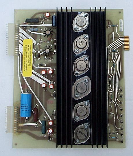
Power Supply #1 Board
#400538-000 Power Supply #1 Board
Board goes in Slot# S4.
This takes the Raw D.C. Voltages from
Floor-Plate and Regulates them to
Following 6 Voltages;
Plus & Minus 5 Volts D.C.
Plus & Minus 12 Volts D.C.
Plus & Minus 15 Volts D.C.
Power Supplies Run-Hot! I Mount 4-Inch Muffin Fan Under Power Supply #1 & #2
Boards Blowing Upward on their
Black Heatsinks for Good Cooling.
Both Power Supply #1 and #2 Boards are Fairly High-Failure Items. When Having Controls Shut-Off Problems, we usually have Customers Send-In these 2 Boards
for Testing, Repairs, & Up-Dating.
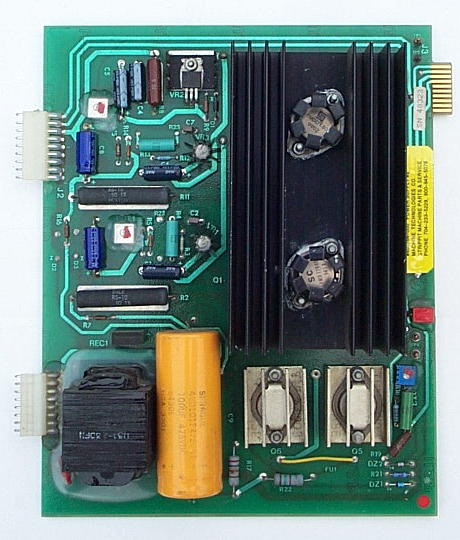
Power Supply #2 Board
This takes Raw D.C. Voltages from Floor-Plate and Regulates them to following 4 Voltages;
Control 24 Volts D.C.
Machine 24 Volts D.C. ( VDC-Voltage )
Machine 12 Volts D.C. ( 1DC-Voltage )
Display 250 Volts D.C.
Board goes in Slot# S3.
There are 2 Versions of this Board;
#400764-000 Standard Power Supply #2.
#400764-100 Standard Power Supply #2
Except that it does Not have 250 Volt Components and does Not Make 250 Volts. Used on Machines that have Display Retrofit that does Not Require 250 Volt Supply.
Note, you can use a -000 Type in place of a
-100 Board, But you can Not use a -100 Board in Place of a -000 if you still have Original Burroughs Display which Uses 250 Volts.
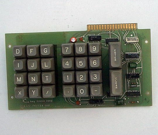
Keypad
#400799-600 Standard HECC80/1 Type Keypad
with Prom Chip.
We Keep All of These
HECC80/1 Type Circuit Boards In-Stock For-Sale
and also
Can Usually Test & Repair Your Circuit Boards.


This page was last updated: May 26, 2025


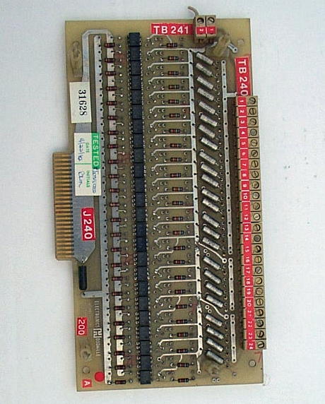
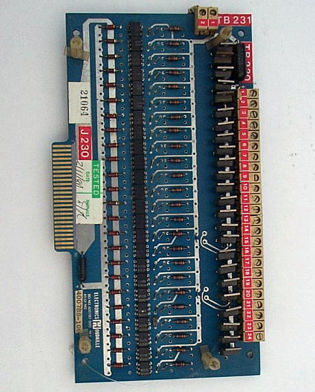
Transition Boards
#400880-xxx Transition Boards were made in Many Different Versions for all the Various HECC80 Controls.
These Boards were used to "Transition" from Hard-Wiring between the Panel Switches, Tapereaders, Etc., to
Ribbon Cables to take Signals to
Control Boards in Cardcage.
All HECC80/1 Type Controls had
3 of these Boards, All were Wired Differently with Different Components.
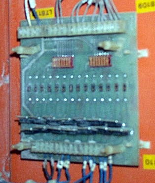
In Top Picture at Right,
is shown the 2 Transition Boards
(2 are Stacked on Top of Each Other)
that are Top Left Corner of HECC80 Control Door.
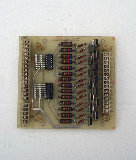
Transition Board at Lower Right is
Located Close to Tapereader in
Middle of HECC80 Control Door.
This Board has Black "Thumb Wheel"
Rotary Switch that Customers Can't
Seem to Find. Used to Set Baud Rate
for RS-232 Communications. We Set Switch to "1" for 300 Baud, which is ONLY Baud rate that Works in
HECC80/1 Controls.
Extender Board
#400322-000 Extender Board
Used by Service Technicians to Extend Out of the Cardcage
a Circuit Board so that it can be
Probed & Tested with
Voltmeters and Oscilloscopes.
Every HECC80 Control Built
Shipped from Strippit Factory
with 1 of these Boards
in it's Cardcage.
Note-1 Capacitor C1 Needs to be Removed from the 3 Boards of a 3-MHZ Square or Sine Wave Excitation System, or Intermittent Zero & Positioning may result.
This is a Very Common Error and I find many Controls with Incorrect Board Versions.
Note-2 The Switch is Only used for a Certain Test Procedure that You, The Customer,
will Never Use. In Normal Operation, it Does Not Matter if Switch is in Up or Down Position, But I Normally leave All 3 Switches "Down".

Note! Strippit used TI (Texas Instruments) Chip Sockets on Early Prom Boards.
These were Cheap, but Not the Best Sockets available. They sometimes did not
"Grip" Prom Chip-Legs Tightly enough and caused Intermittent Bad Connections.
Bad Connections could cause "Check Sum" Errors at Start Up and Intermittent Control
Failures While Running with Red LED Lights Lit-Up on CPU Board.
All Front Panel Lights would be "ON" as CPU Board was No longer Running.
TI Sockets have Small Rectangle-Holes where Chip-Legs are Inserted.
Later Boards were Manufactured with "Machined-Pin" Chip Sockets. These Sockets can be Identified by Gold-Plated Round Holes where Chip-Legs are Inserted. These Sockets Grips Chip-Legs Better and prevents above Problems. Old Sockets are Very Difficult to Replace without Damaging Circuit Board, and I advise Replacing 2 Prom Boards with New Boards with Machined Pin Sockets Sockets!
Note! With our New Digital Oscilloscopes we can Capture & See Power Problems that we always Suspected Existed, but could Not See with old Analog Oscilloscopes.
Power Supply #1 & #2 Circuit Boards have some Designed-In Deficiencies that sometimes cause Power Supplies to Break into Oscillations. These Oscillations
cause Many Intermittent Controls Problems and Control Shut-Downs. With Any
Intermittent Control Problems, First Place to Start is to Send-In these 2 Boards for
Rebuilding, Because CNC Control Cannot Function Without Good Clean DC Power!